|
This
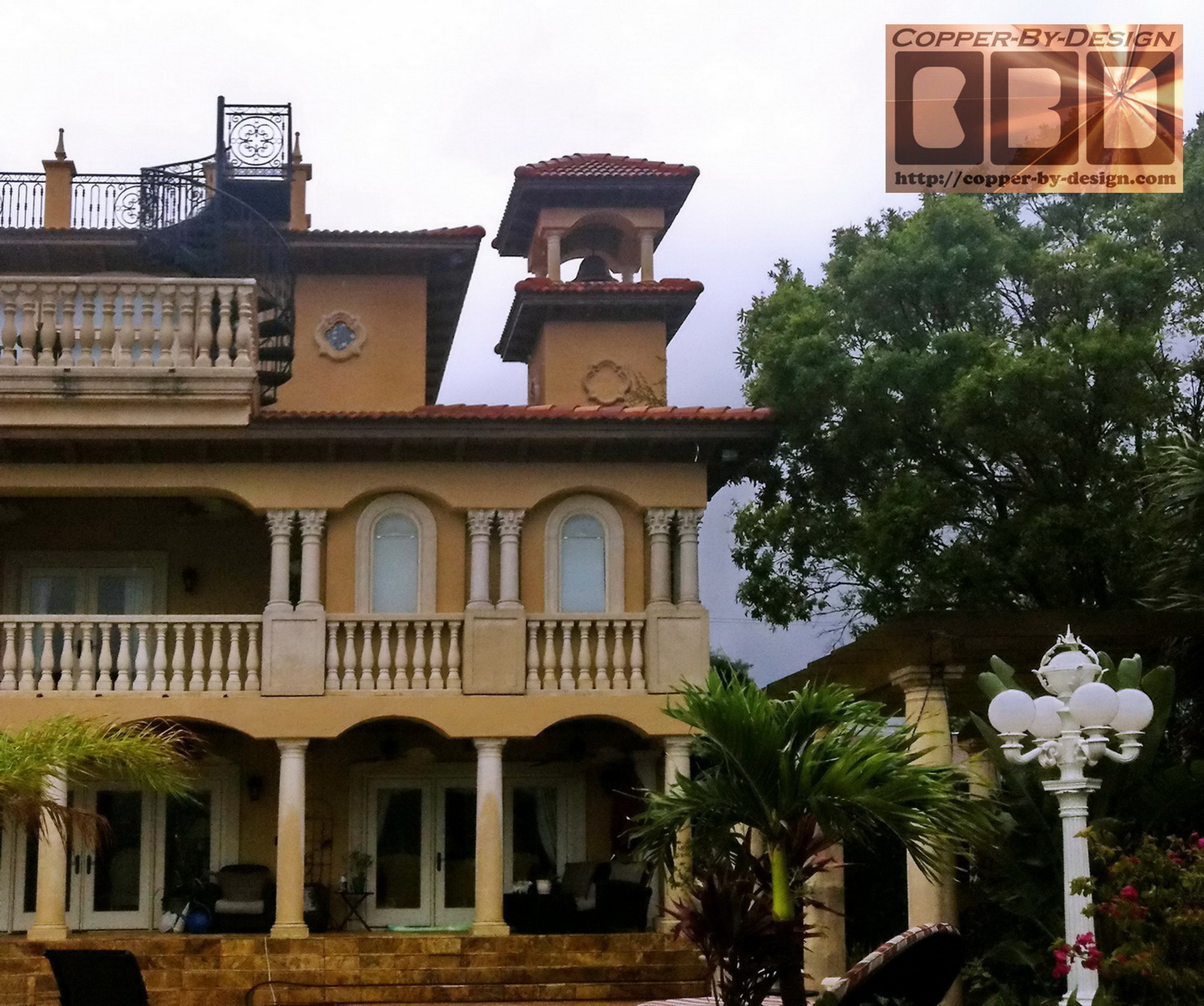
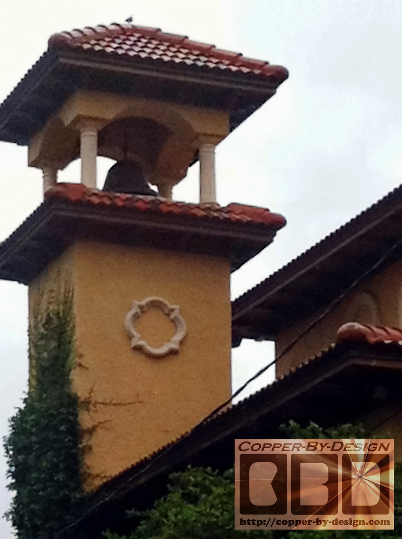
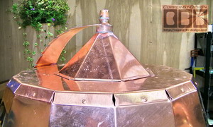
project was inspired by this photo of an 8 sided bell shaped
copper dome built by some other craftsman. David
Nelson in Tampa, Florida sent me the image on the left to show
me what he had in mind for the chimney cap cover as part 2 of 2. The other chimney cap
he had me build resembles a Bishop chess piece:
http://copper-by-design.com/cc/cp/Nelson.htm
He first contacted me
4/29/09 and we gradually worked out this project through
exchanging over 70 e-mails
along with several diagrams and photos like this photo
on the right to show this bell stretched to match his limited specification
to fit under this tiled roof over his chimney pipe along with a
24" tall finial.
 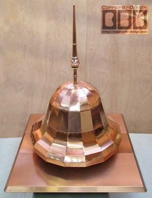
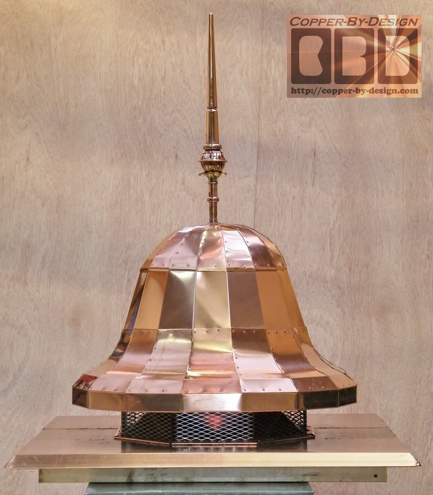
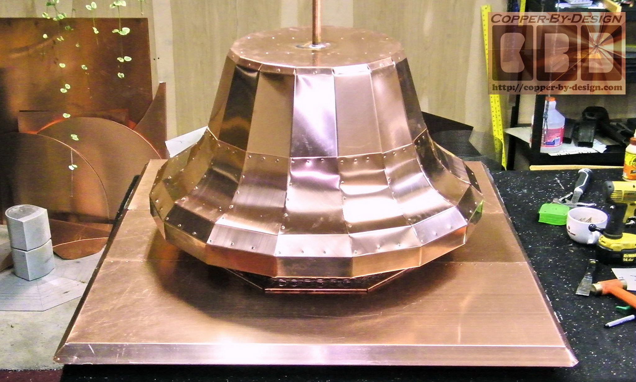
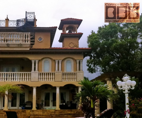
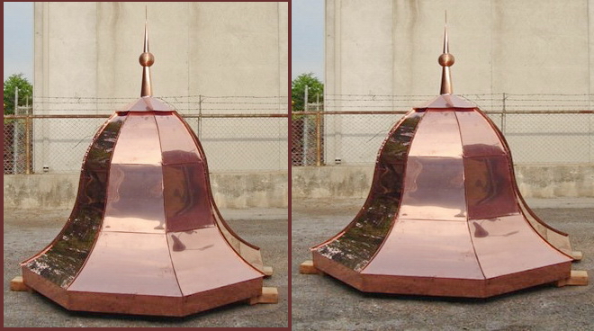
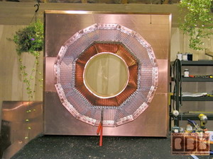
I just before fabrication began I volunteered to build
this with twice as many sides, so this has 16 faceted sides,
instead of just 8. This helps make this look a lot more rounded,
as you can see here. This enhances the bell shape without
generating a much greater cost to form this in a completely
circular manner by stamping or hammering the copper to bend in 2
directions.
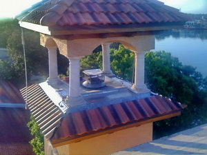 
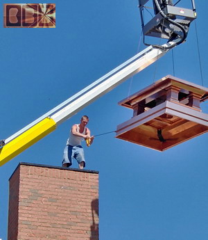
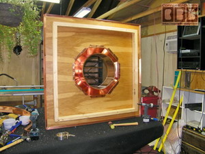
This is the structure I needed to make this fit inside.
I had a limited height inside of just 57". It is rather trick to
do this all remotely; relying on just the clients measurements.
It is also important to design this with a near invisible
attachment as well.
|
|
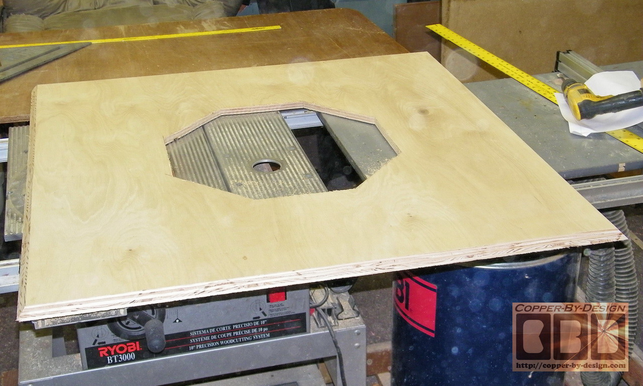
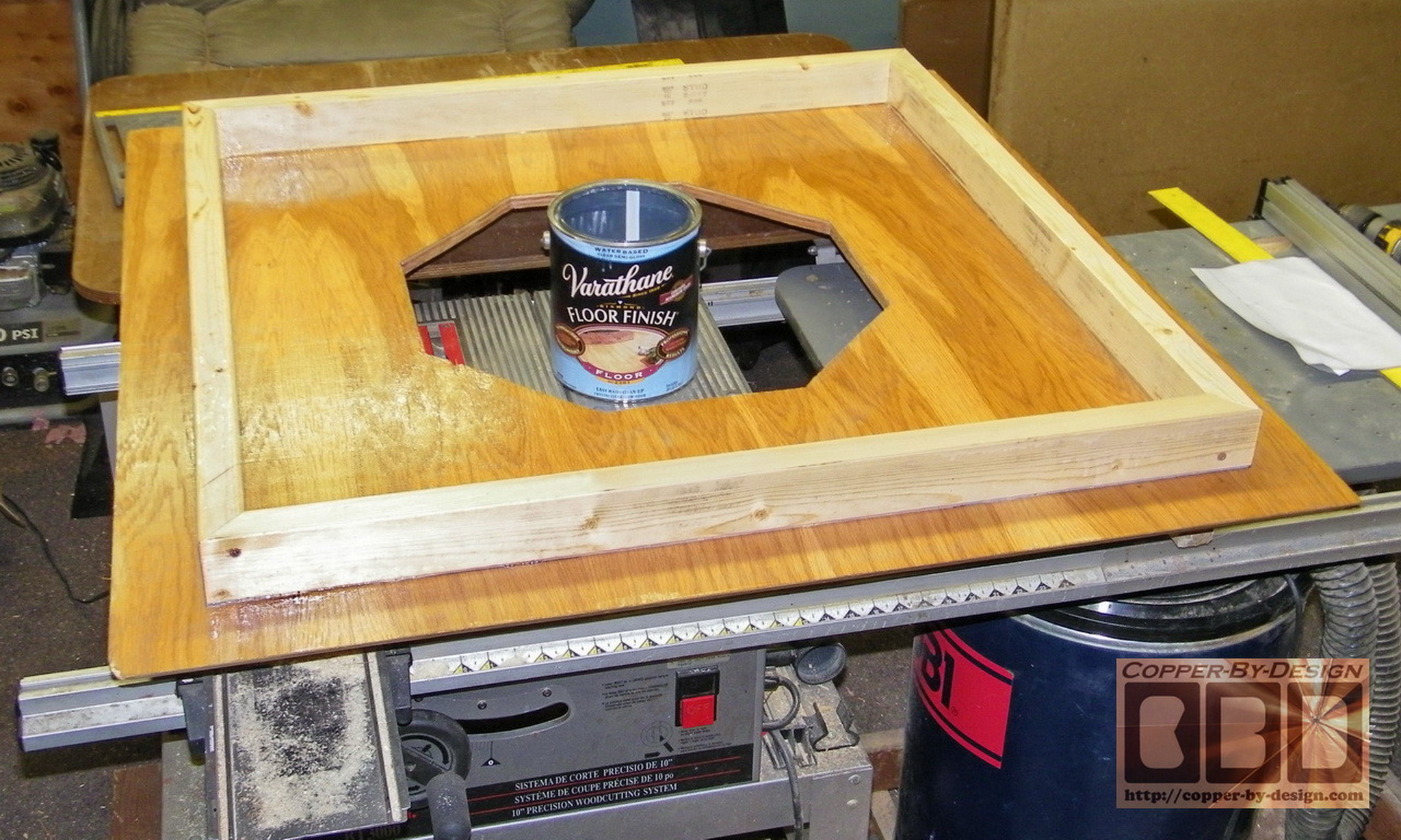
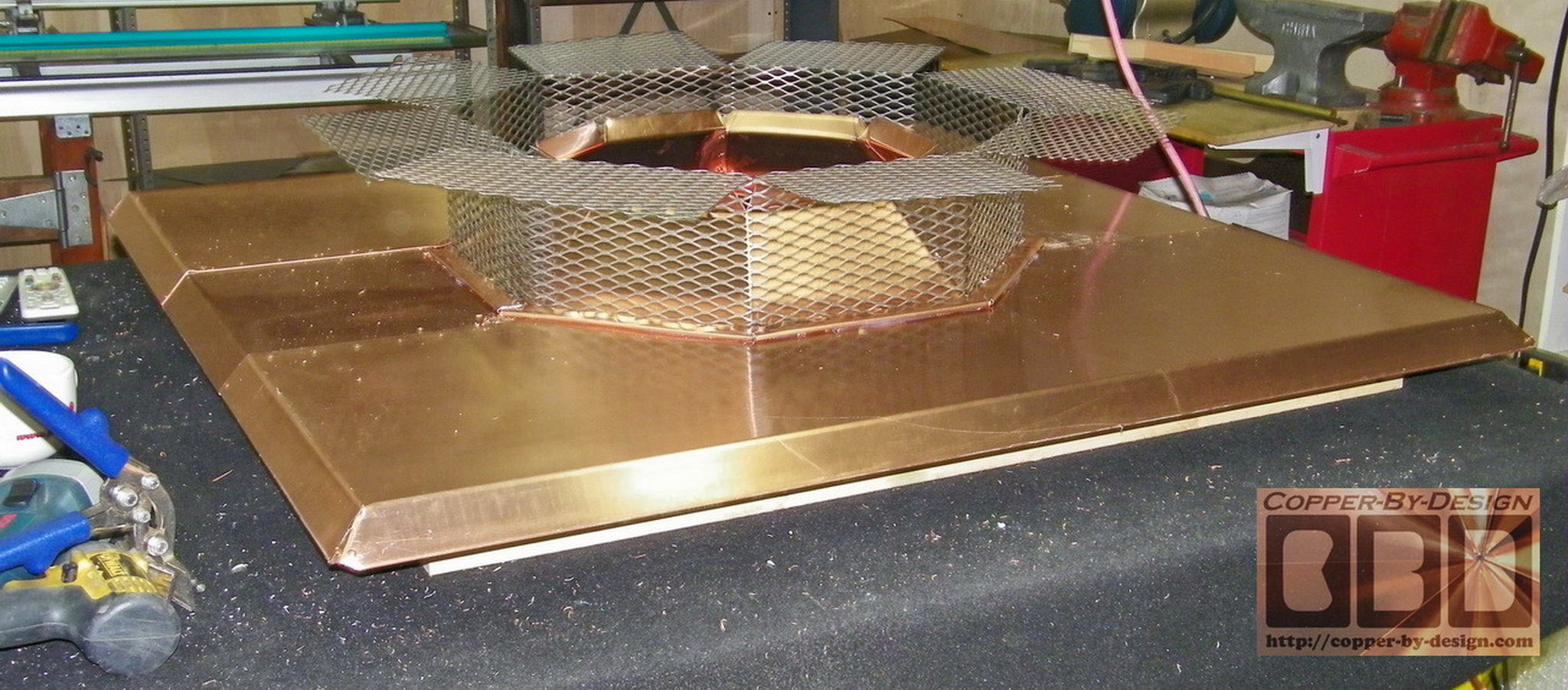
Building the Base Pan:
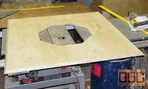 
This show the varnished 3/4" oak plywood I use
for the base under the pan that will help anchor this down in a
strong wind storm. I bevel cut the sides at a 45 degree angle on
my table saw for added style. I made this inset rim to attach the
plywood from underneath and also to raise up the pan, so it can shield
over the top edge of the roof tiles surrounding it.
 
Then it gets covered with this copper skin to keep it
shielded from the elements.

|
|
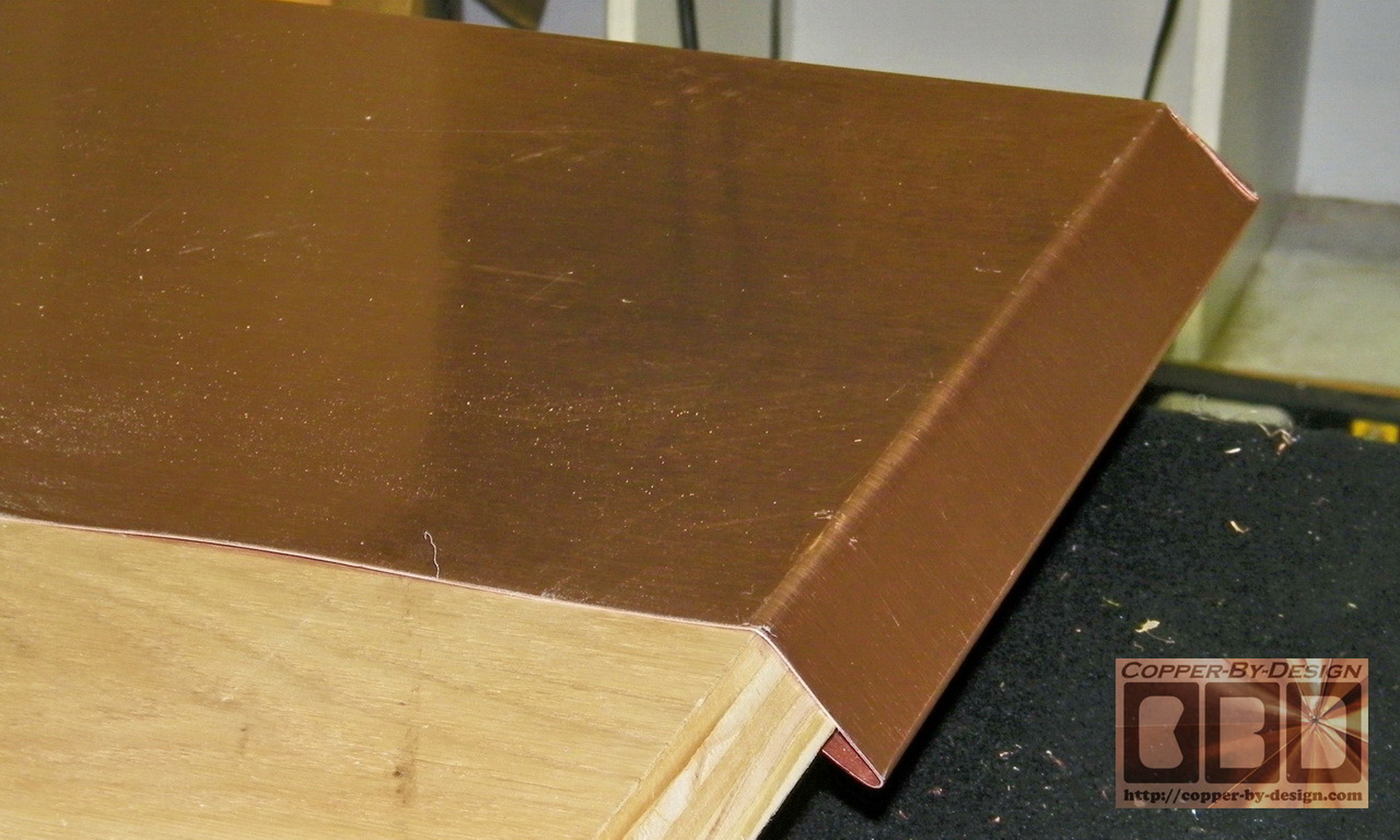
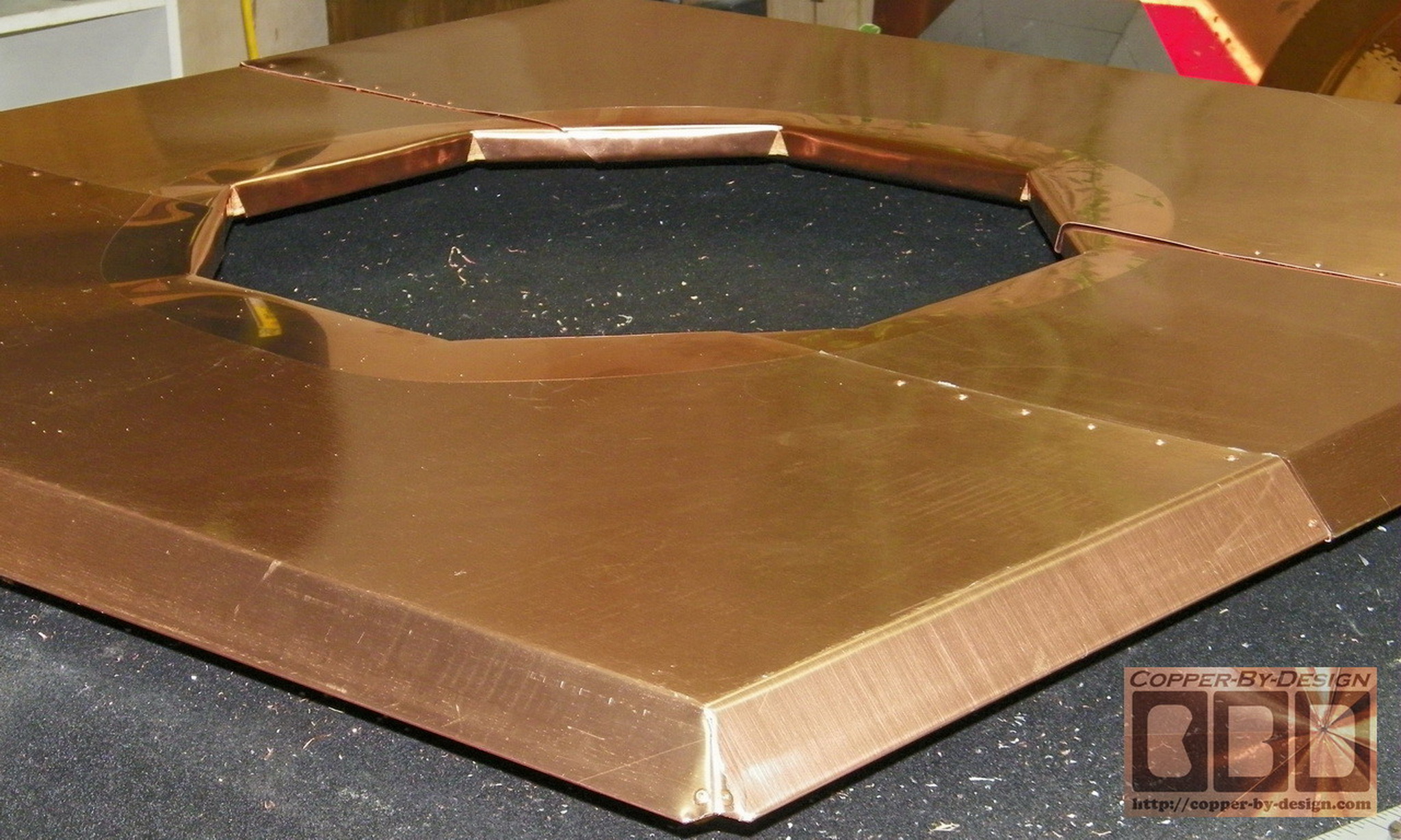
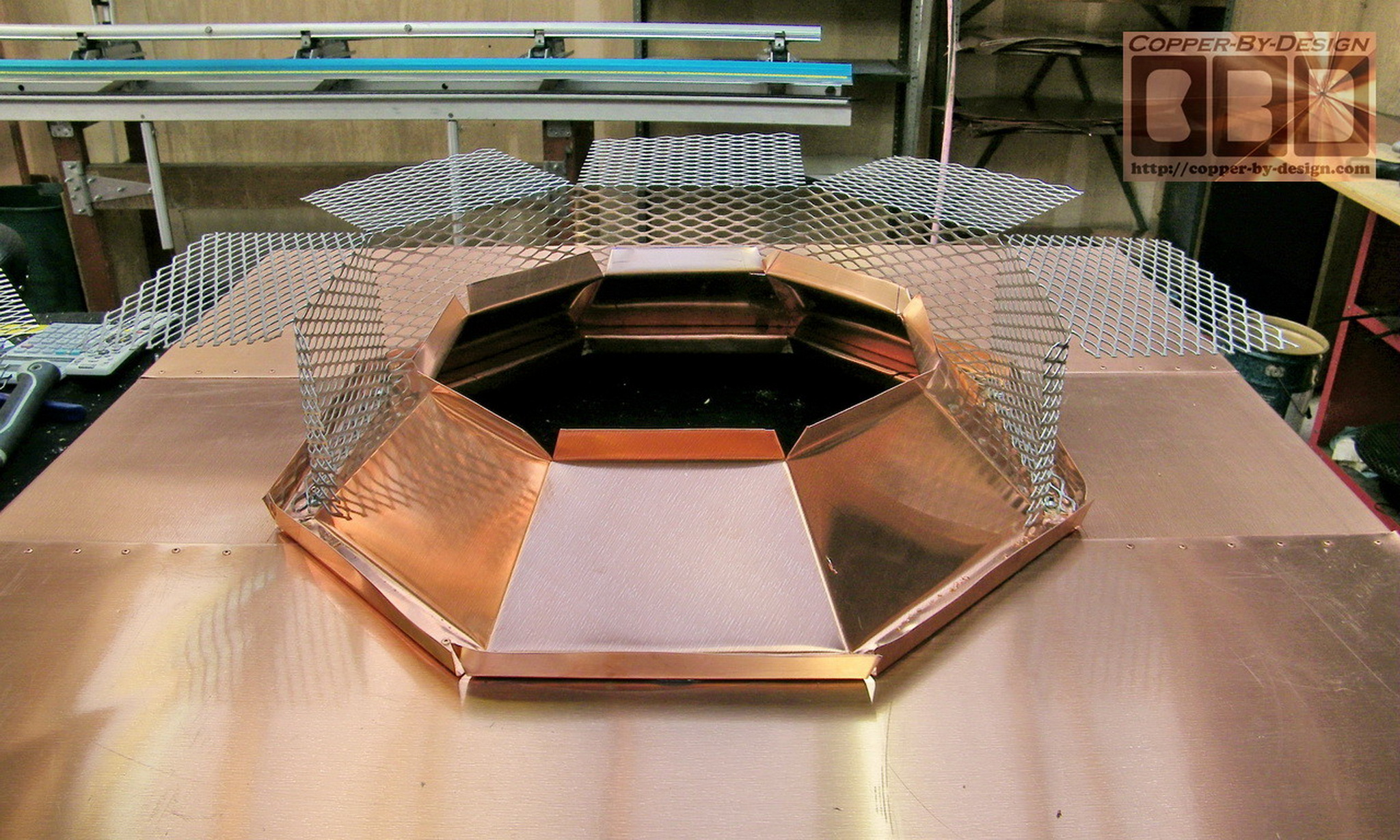
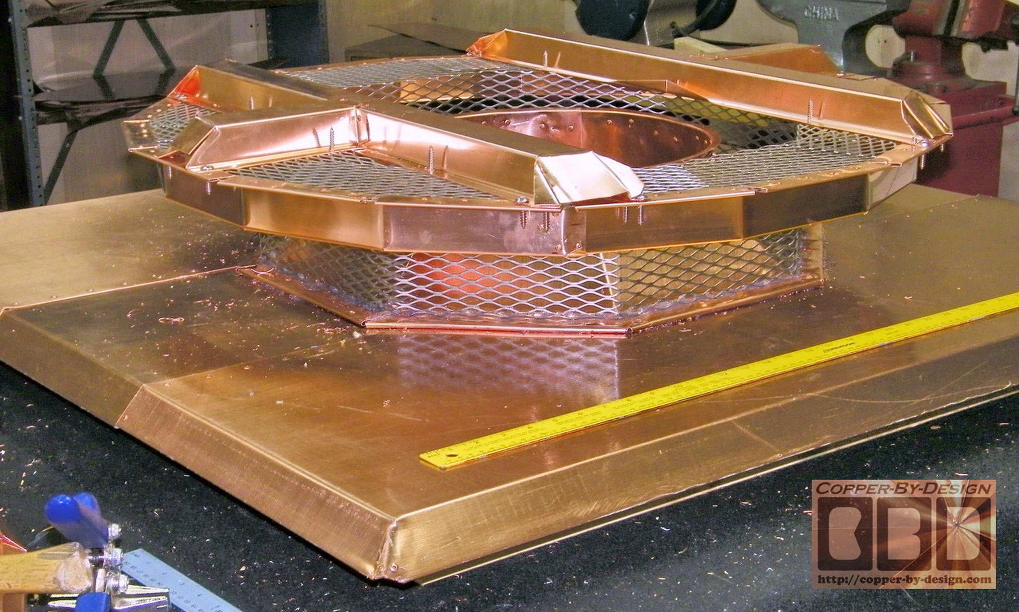
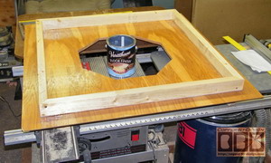
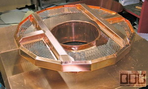
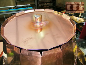
Covering the Base Pan w/copper:
I needed to make this rain shield in the
middle to surround the flue pipe. The 6" tall spark arrest
screen vent area around this is made with a 16 gauge stainless
steel expanded metal screen in an 8 sided unit that the whole
bell will be supported over to look as if it is suspended above
the pan 4", so this exhaust area was very limited.
I needed to make sure there was enough
exhaust vent area displacement, so I had to make the area
horizontal as well to
add more ventilation surface to this design.
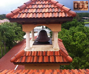
The client approved this design and has been very pleased with the
results after seeing it in these photos I had sent as I built
it.
|
|
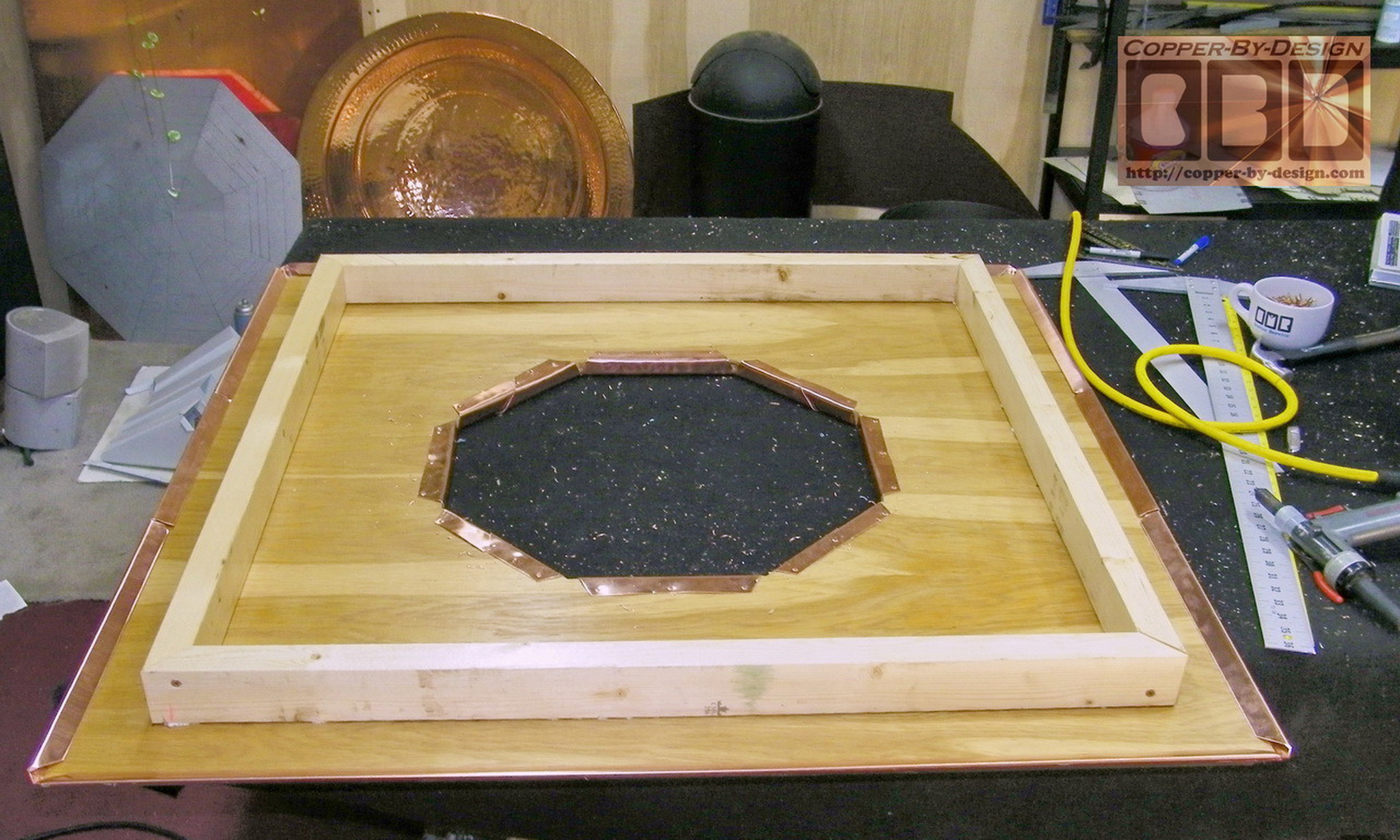
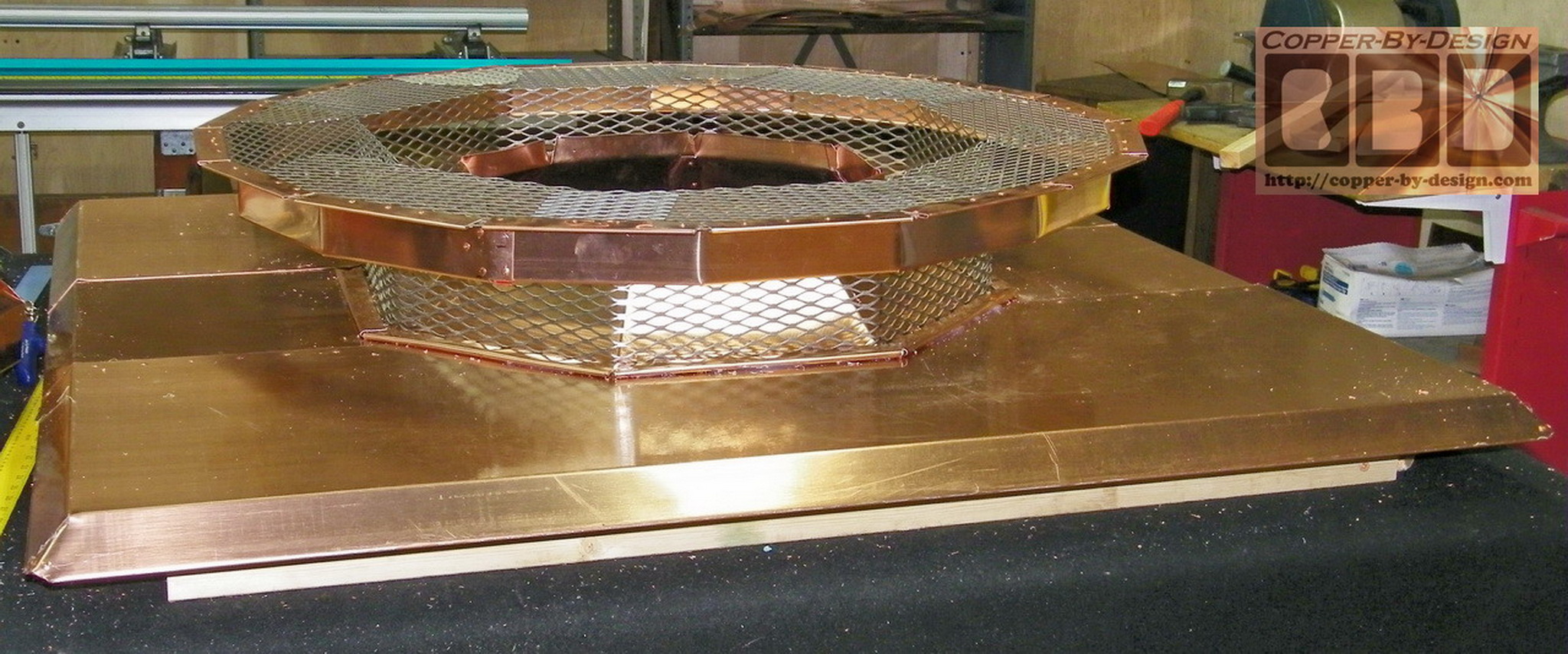
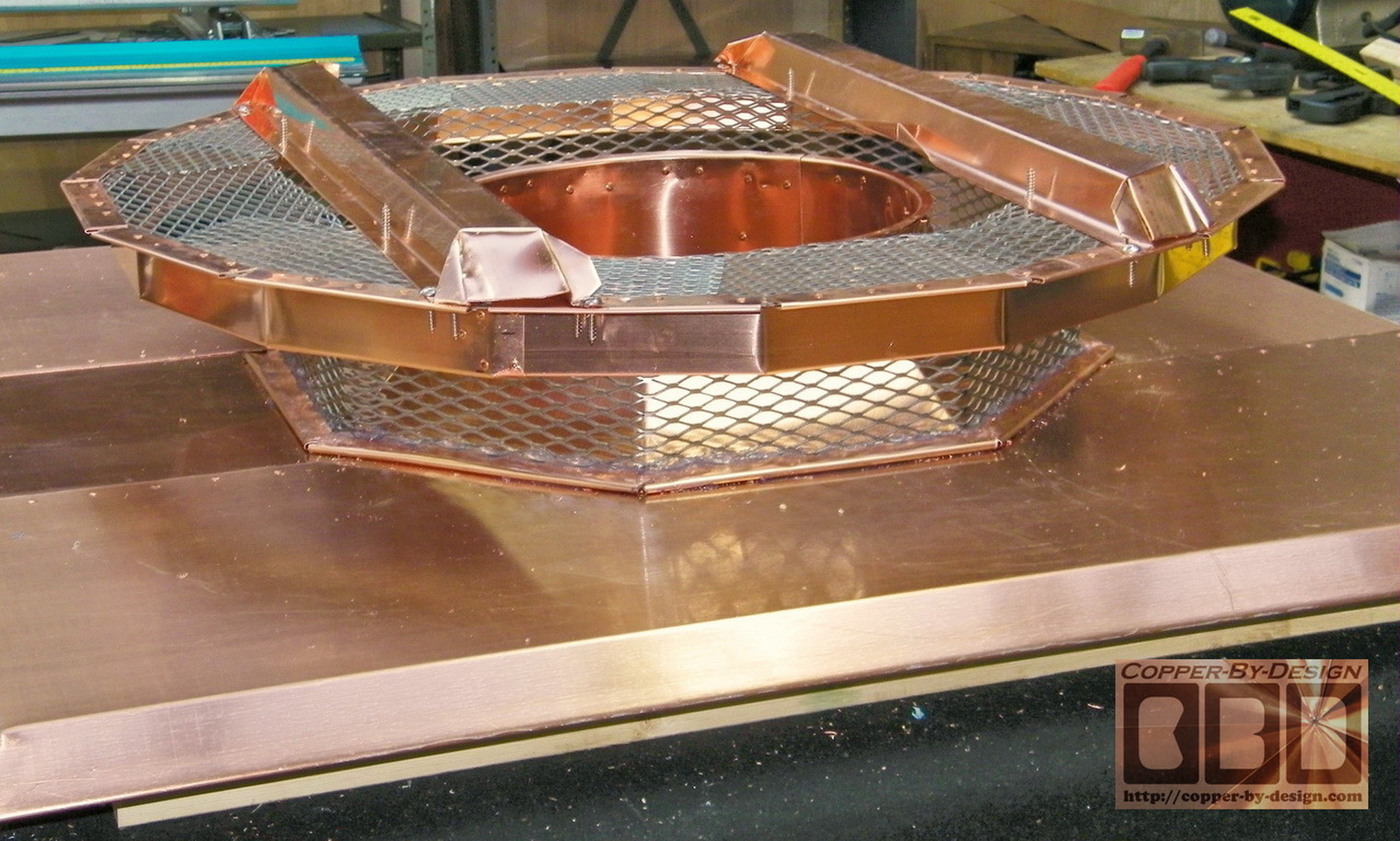
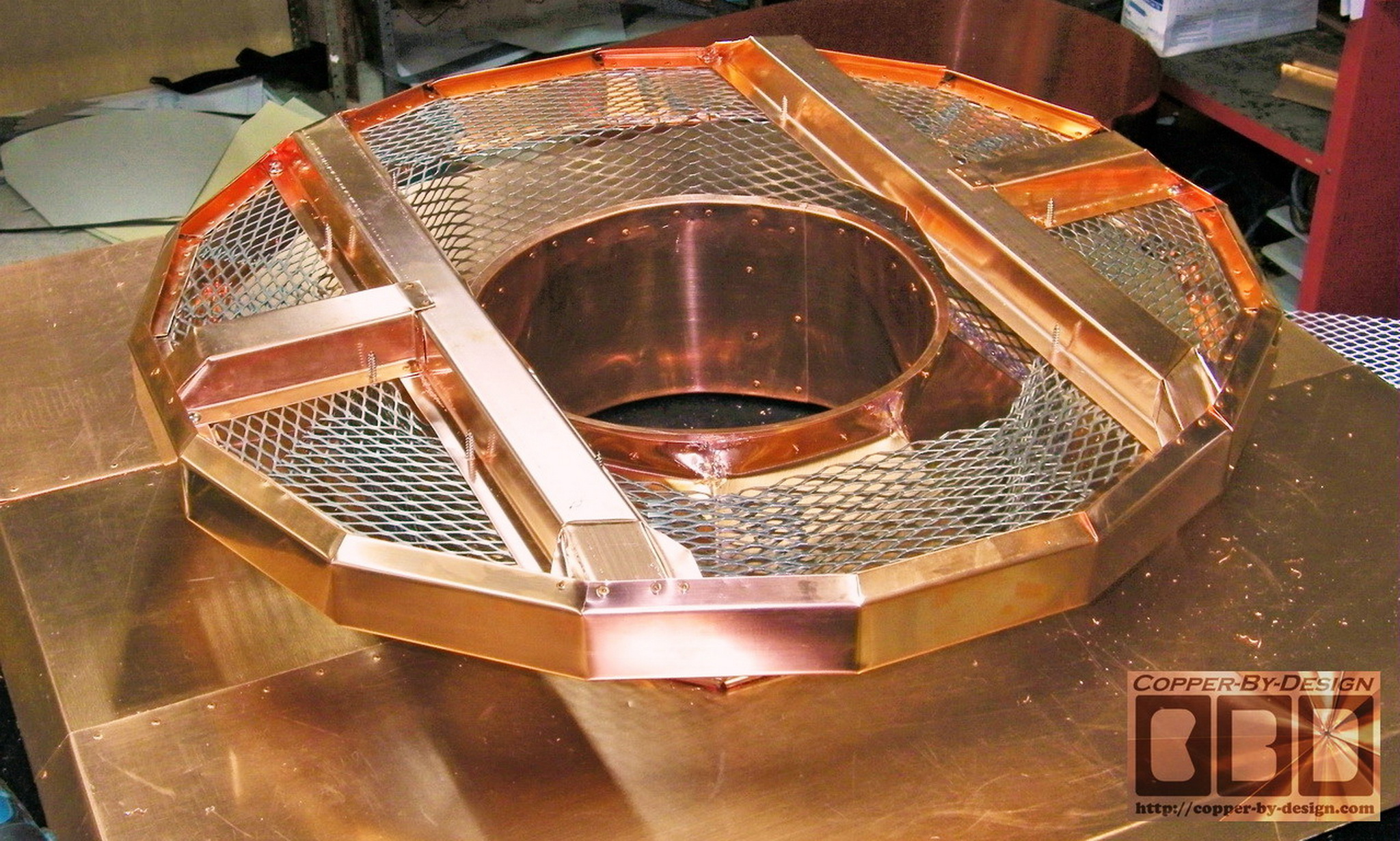
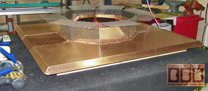
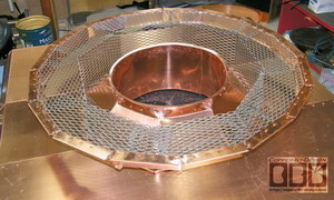
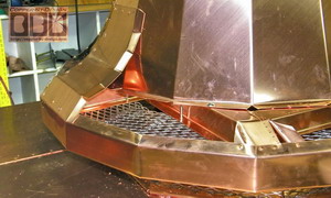
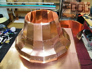
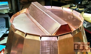
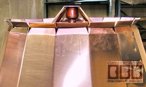
Building the Bell Support Base/Flue Vent:
The hood exhaust head to set over this has to
transition from an octagon to a 16 sided shape to look more
cylindrical. These screens are what I get my
hands lacerated on more than any other aspect of my work, so
it's important to wrap all the edges of this SS screen in copper
sheet metal, so there will be no sharp edges exposed once
completed.
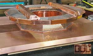
As all these pieces get fastened down it
gradually adds more and more strength to this structure, but it
still needs some cross bracing. The client had me add this 14.5" flue
liner. I made this circular with a rim on the top and bottom
edges for added strength. It is connected with 32 rivets through the rain shield
|
|
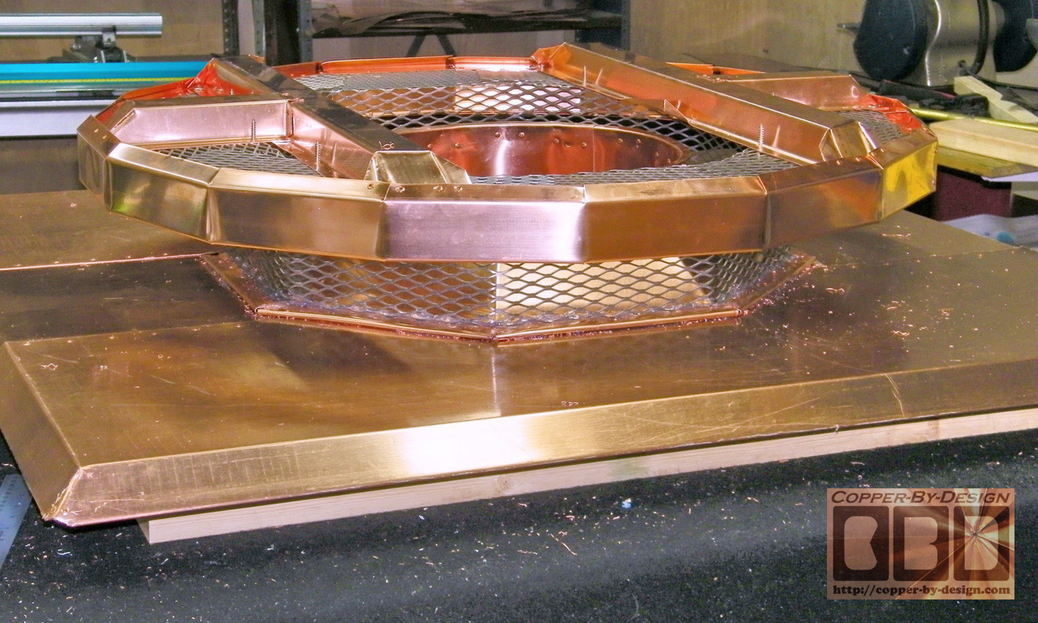
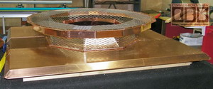
Building the Support Braces:
It took me a few days just to build these
32oz copper roof support frames and attach them securely. I designed these
where the exhaust can still flow up under these braces.
Then the one piece 34" wide outer bell rim gets made and
attaches outside
these support frames and the edges get folded under the SS screens
frame work.
As usual this was a bit more tricky to build
than I had imagined and not something I can charge more for, but
I feel it was worth the extra effort towards the Client's
long-term satisfaction. It is much easier to build it well now,
than to have to rebuild it later on.
|
|
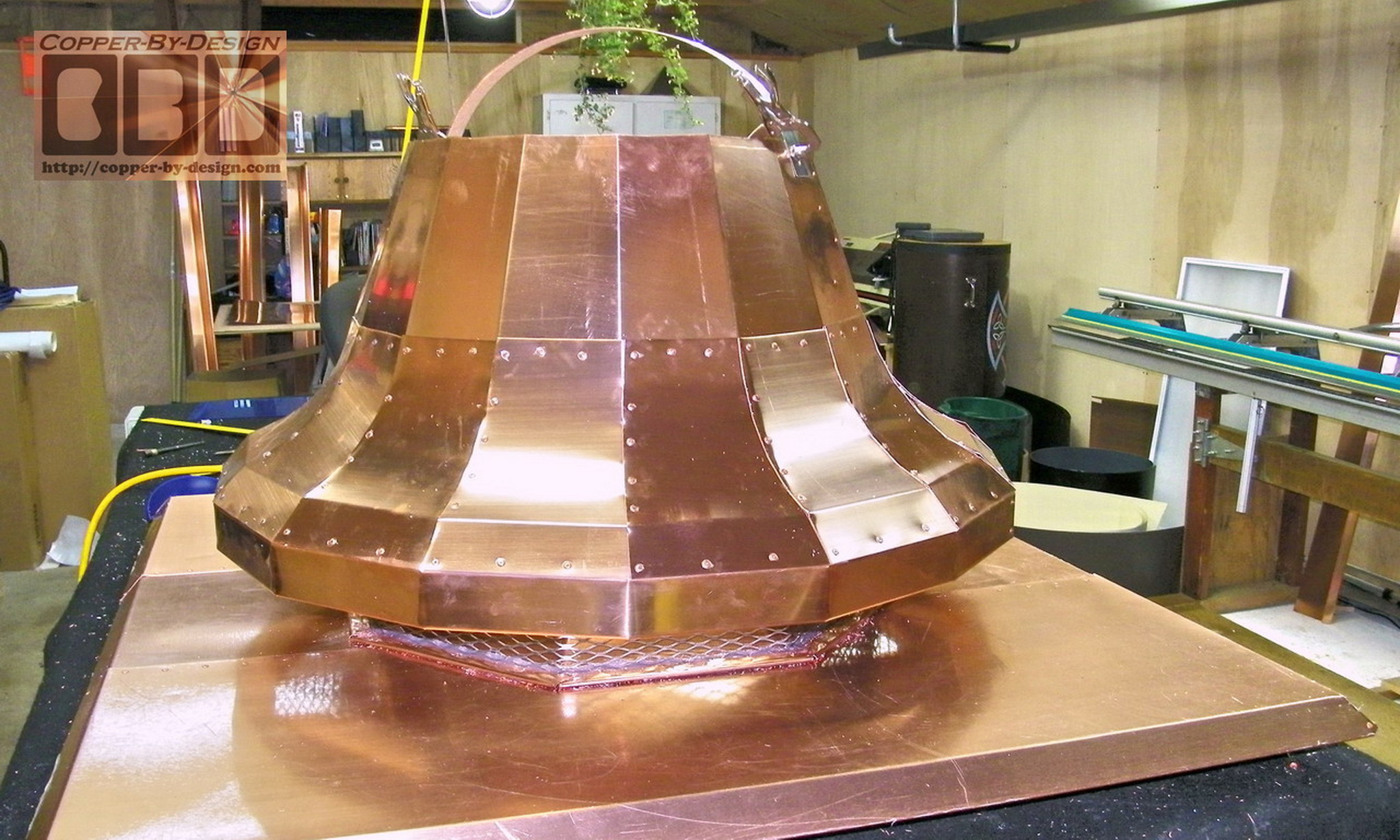
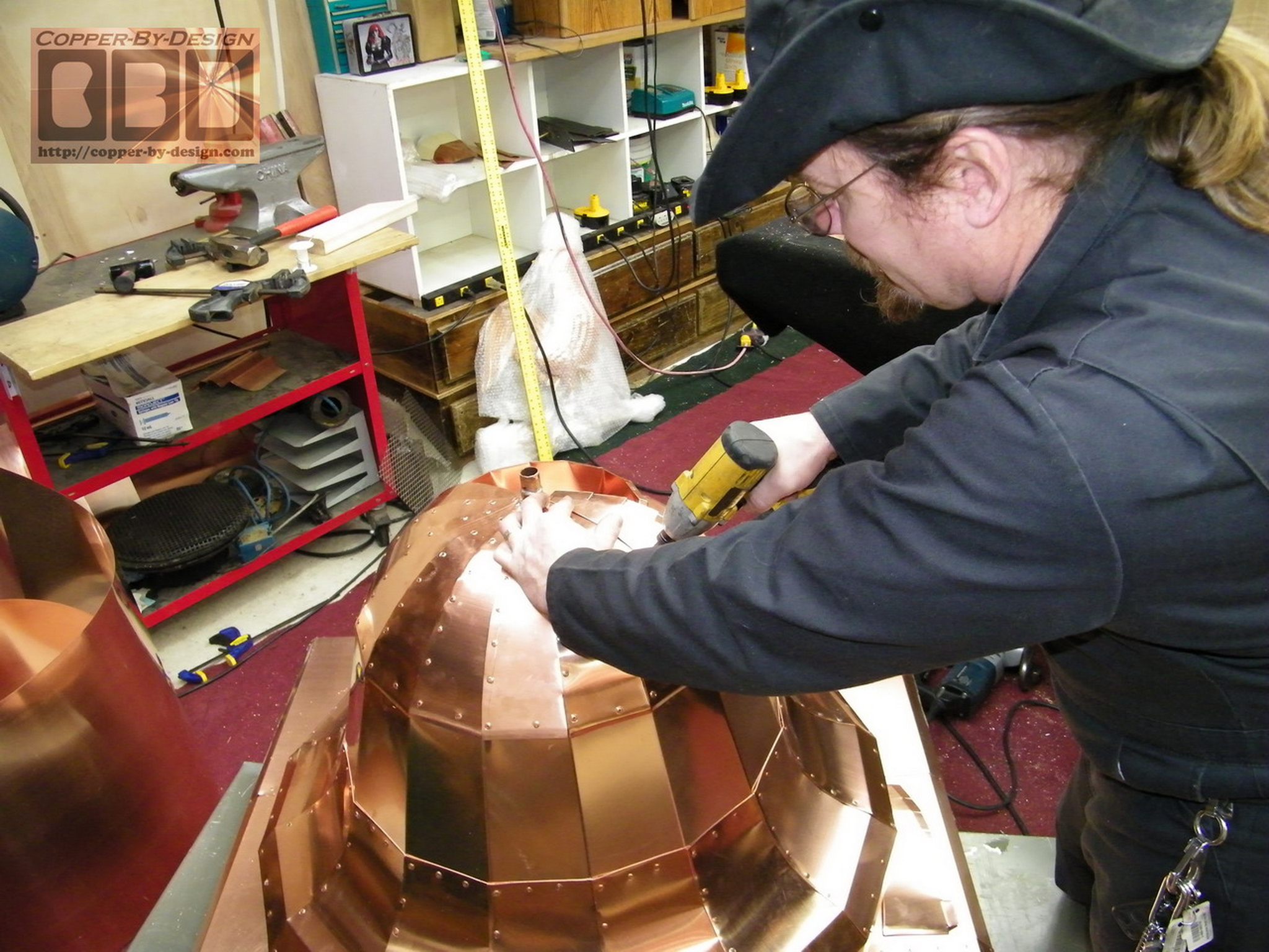
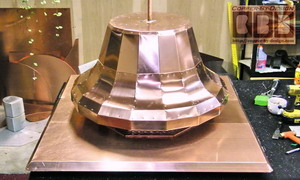
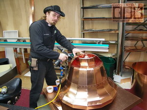
Building the Bell:
Here is the decorative copper bell mid-section
being formed in one single sheet of copper and attached right
over the cross bracing. I thought the whole weight of the bell
would be resting on the outer edges of the bell's rim, but this
construction made the thicker copper cross bracing less
important. I am often guilt of over-kill in many aspects of my
work and this is a good example.
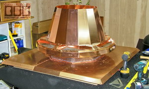 
I was going to just make a simple slope
from the outer edges up to the mid-section, but at the last
minute while forming the aluminum templates I came up with this
added bend to give this a bit more ornate styling.
 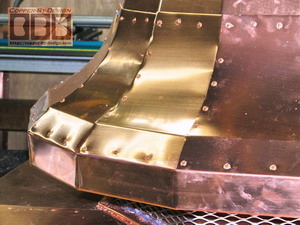
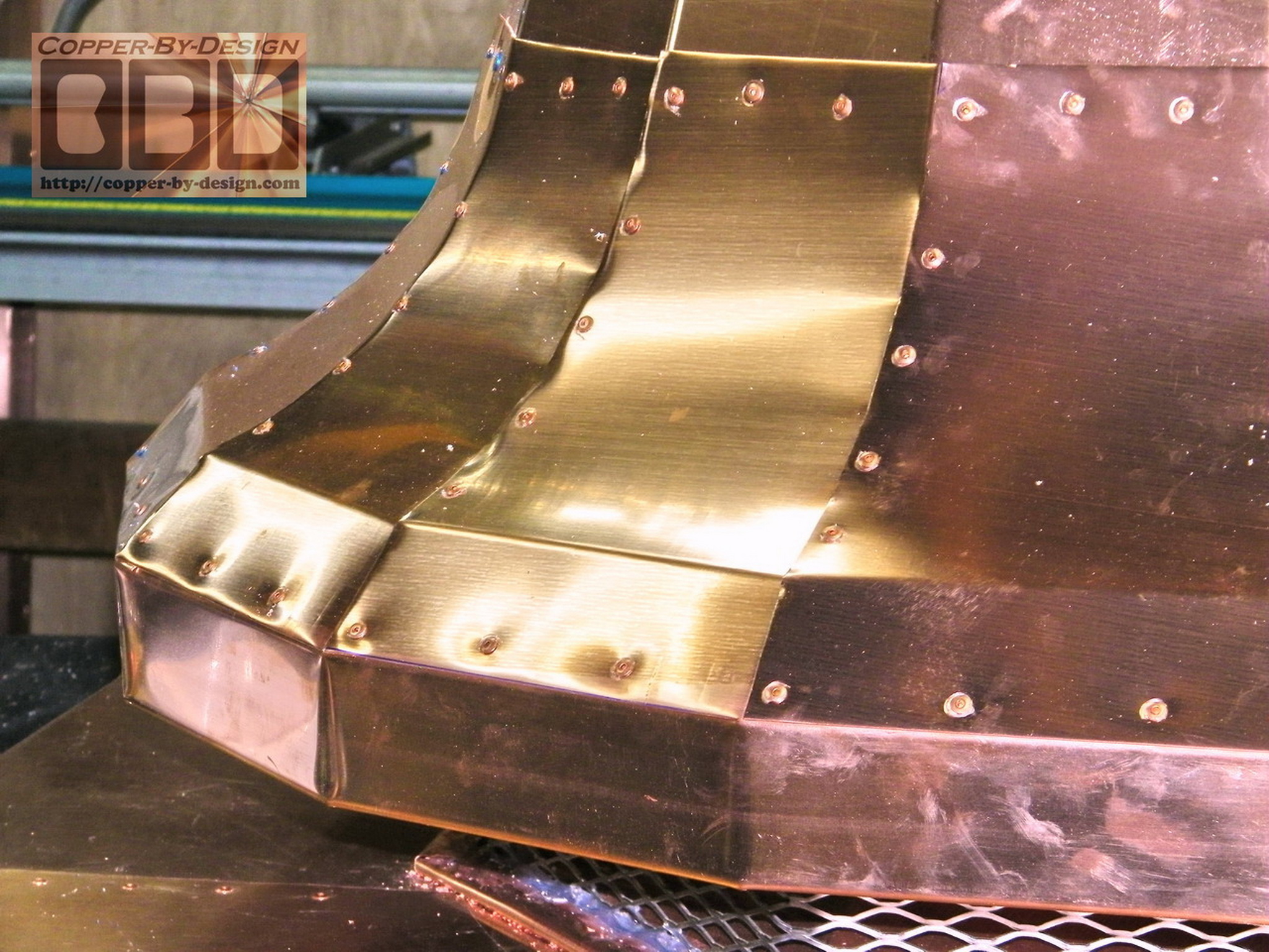
Here is some shots of the outer bell hood being formed. The many
rivets are very noticeable at close inspection, but after this has tarnished to a dark brown
they should be a lot less noticeable. Solder may be a way to attach
these without rivets, but it would not be able to withstand 1/4 the
heat that copper can handle. Everything is only as good as it's
weakest part.
|
|
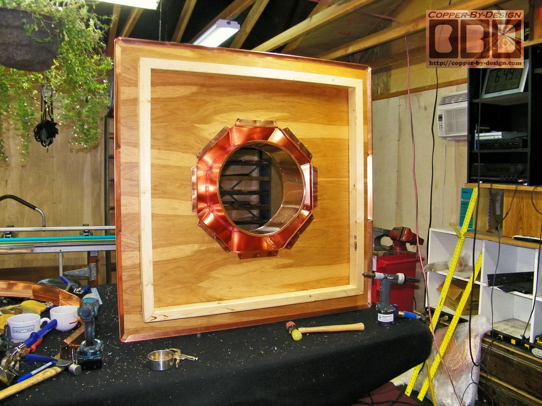
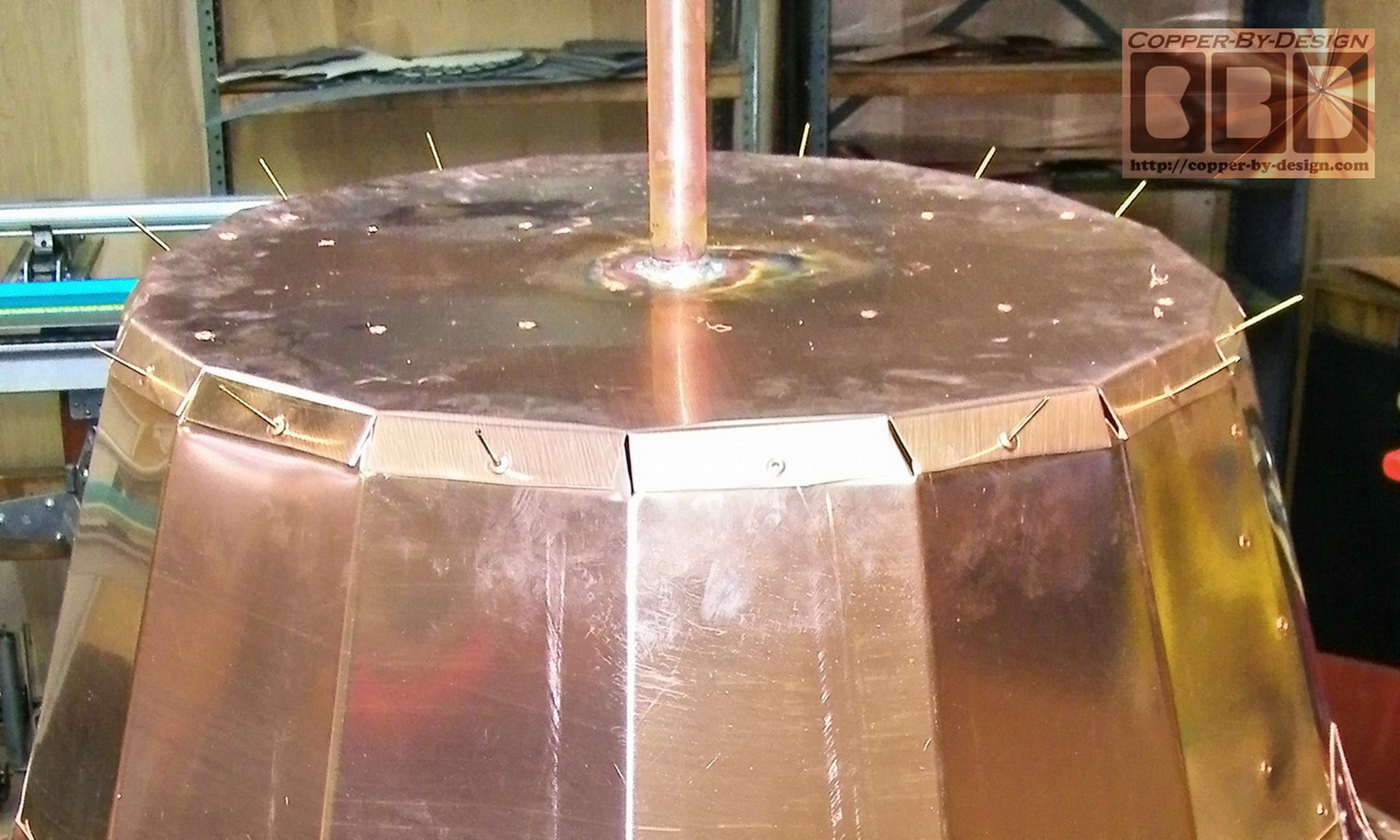
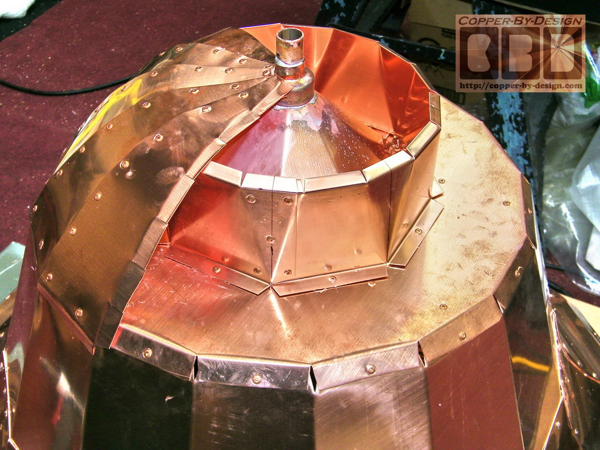
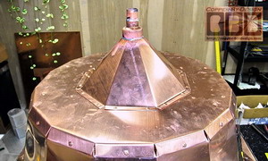
Building the Finial Support:
Here is some shots of the finial support pipe being formed and
securely attached within the dome of the bell. The bottom of the
pipe is soldered together with a double cap system and attached
inside this plate that is attached over the bell's mid-section. The
right photo shows this plate upside down over the bell.
Then there's this cross brace attached
over the bottom caps and riveted together.
Then this is attached over the bell's
mid-section.
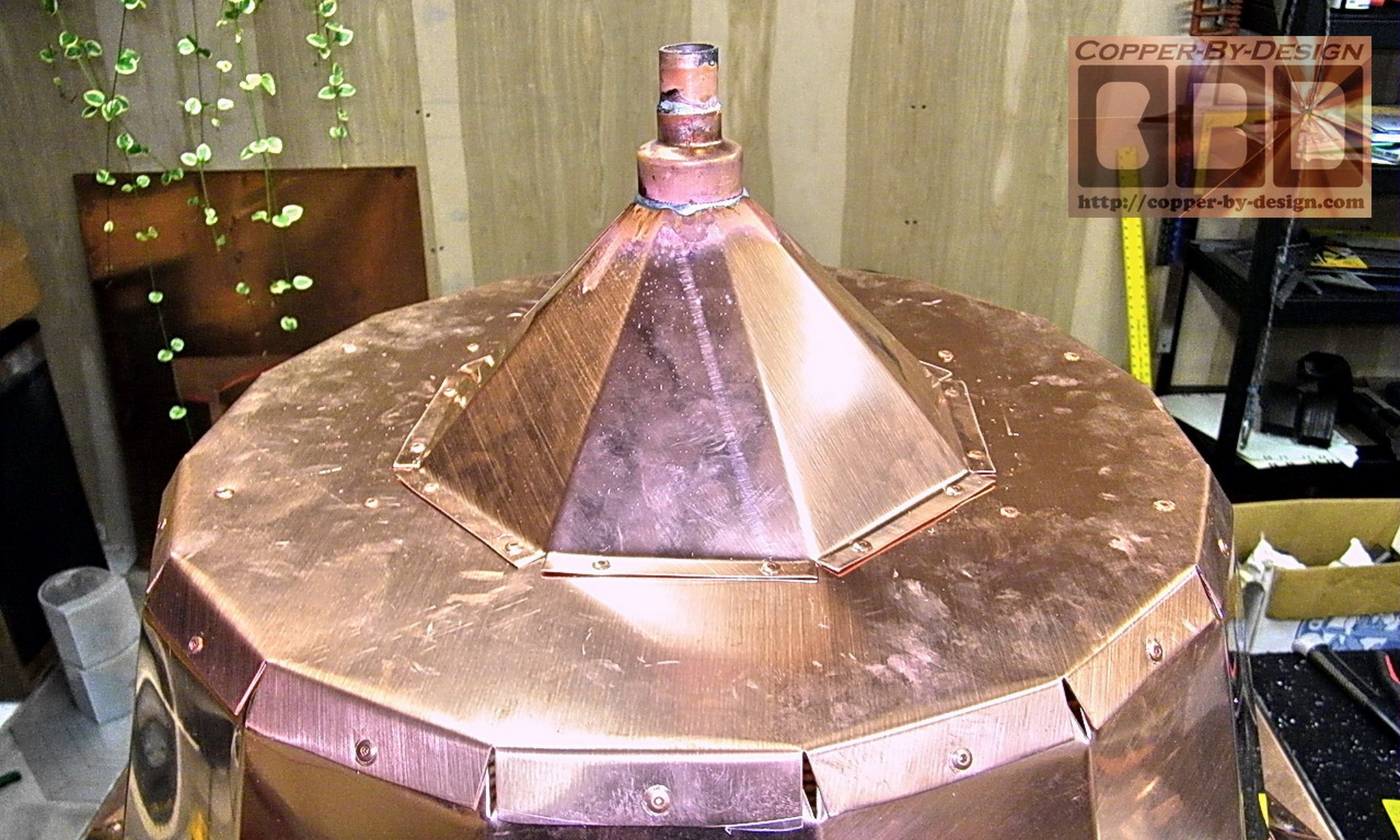
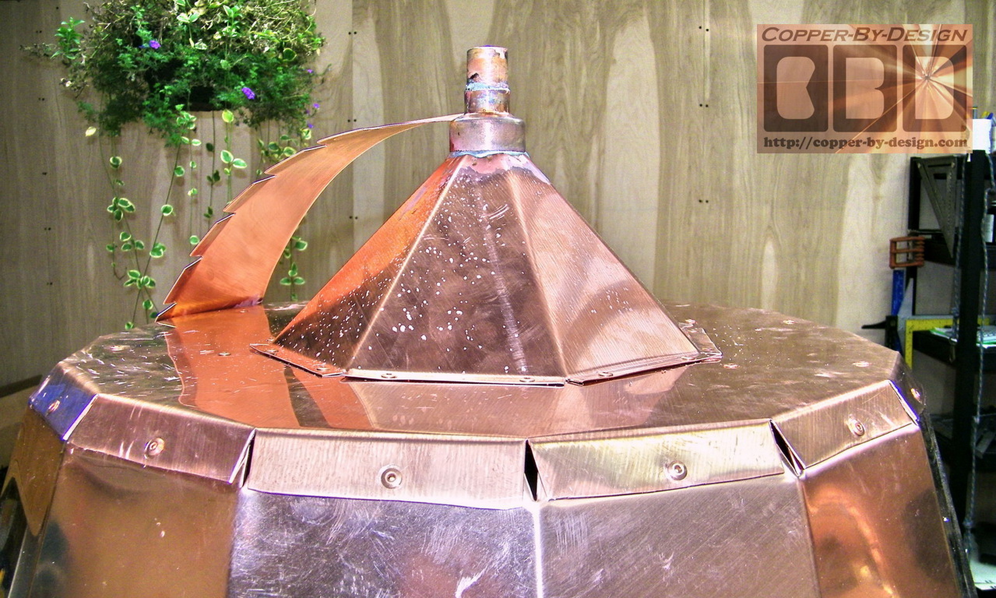
Then I made and attached this cone
over that plate to help support the top of the pipe.
|
|
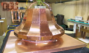
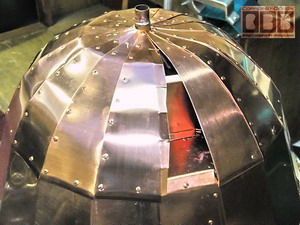
Building the Finial Support:
This support also gave me a narrow
surface to attach the 16 dome pieces to in the middle. I decided
to also add this middle support ring for the dome.
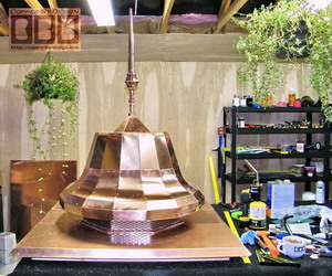
As you can imagine this is a rather
tedious process. It was not necessary to
seal these sections with solder of caulk, since this will be
sitting under a roof cover. Even if hard driving rains were to
splatter over this dome the plate below will channel the water
out to the edges of the bell anyway.
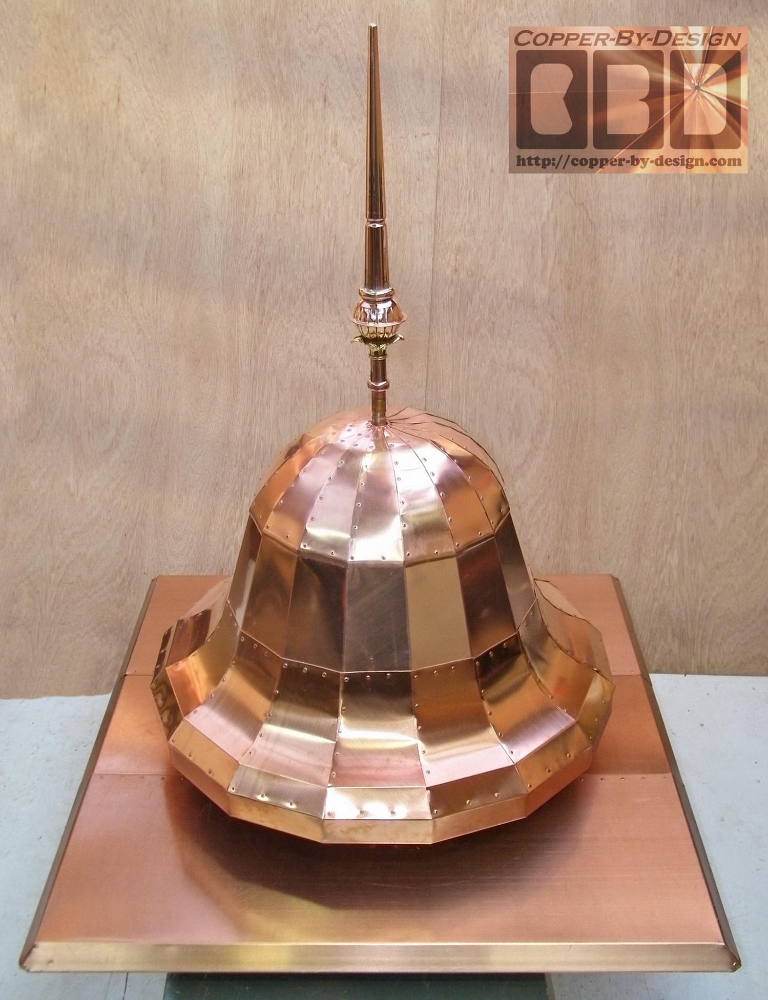
Here is the last pie section needing
to go in to complete the dome cover, and a photo of the final
assembled bell with the finial in place. I had to do some work
to adapt the finial here to work the way I wanted it.
|
 Here is
the detailed weights and cost break-down I had kept track of
during this fabrication: Here is
the detailed weights and cost break-down I had kept track of
during this fabrication:
115#
total weight w/brass rod & finial
185#
weight of the crate
300#
total weight of crate w/contents
111.6#
weight w/o brass rod & finial
-
9.7#
2x3 wood
weight -
12.67 ln'
-
24#
oak
plywood weight -
11.12 sq'
-
5.2#
SS screen weight -
8 sq'
-
18.9#
copper pan cover weight -
15.12 sq'
=
53.8#
copper weight
x 0.8
=
43.04 sq'
20oz copper
x $40 sq'
=
$1,721.60
for copper
bell portion
+
$145.98
for
24.33 ln'
of 2x3 boards x $6
+
$166.80
for
11.12 sq'
of 3/4" oak plywood x $15
+
$472.50
for
15.12 sq'
copper pan cover portion x $ 25
+
$200
for
8 sq'
of 16 gauge SS screen x $25
+
$300
for the custom wood shipping crate
+
$400
truck freight home delivery w/lift-gate service
=
$3,701.88
grand total for this part of their project
-
$2,500
paid 9/17/09, which left a balance of
$1,201.88 |