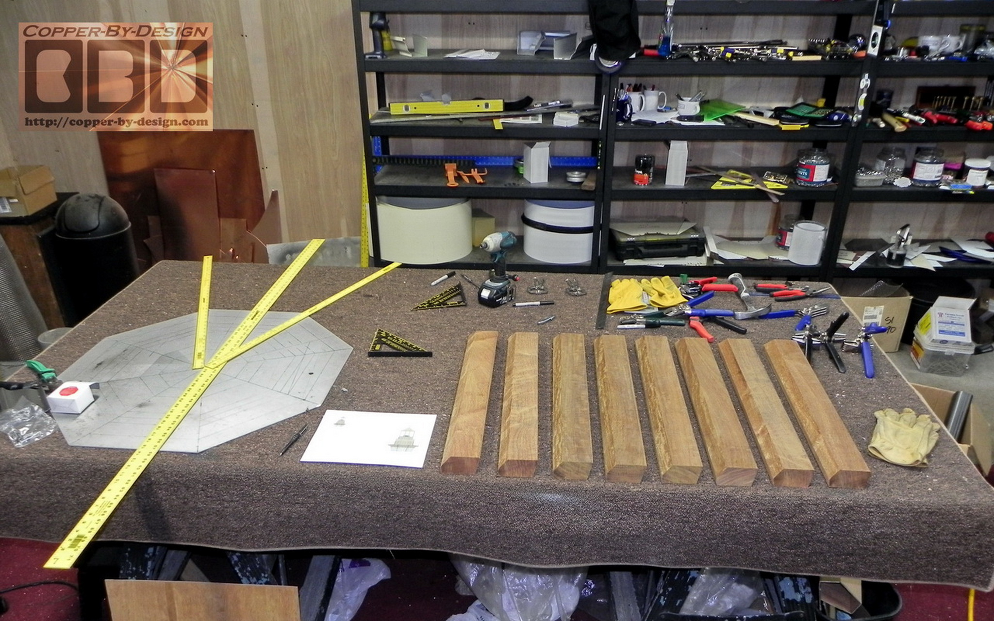
The Pagano Custom Copper Lighthouse Shaped Chimney Cap Details & Photo Page

Seneca Falls, New York (5/10)
Updated 6-3-2010

Company
Profile
Roof Caps You are here Chimney
Caps
Scuppers Gutters Shipping

Contact Info


.

This is a more detailed lighthouse style chimney cap I built for Robert and Sue Pagano in Seneca Falls, New York. He contacted me on 1/31/10 and through exchanging 51 e-mails and several diagram revisions we got the details worked out by 4/22. He had an outdoor fireplace built behind their lake home on the patio. This design has been a collaborative effort between the owners, the architects Guy and Lee, a lighting specialist John, and me of course.

Donahoe Architectural Design Ph# 315-673-2883
60 East Main Street-Suite A, Marcellus, NY 13108

Niggli Associates, Inc. Ph# 585-426-5940
2690 Chili Ave., Rochester, NY 14624

The Client asked to not show the cost here, but it's OK if you contact me for it. I can say he saved over $3.3k off the cost for having me make such an amazing project and adding more copper than predicted.

Production began 4/23/10 w/completion proposed for May 14th to have plenty of time to have the lighting finished and installed before Memorial Day, but this was not able to ship until the 20th. We were able to put a little rush on the shipment, so they were able to get it the morning of the 26th and got it installed the next day.

I had told the client this may take me a month to build. That was before we had revised 5 diagrams to work out all the details, which changed this project to something about twice as complex and costly. I wound up having to work past dark many evenings and through weekends to complete this in time, so they could get it installed before Memorial Day.

Over the course of this fabrication I had shared 90 of the 115 photos I took, and uploaded 5 videos on YouTube to show them how the light test looked late at night, since still photos would not represent it properly.  Below are 3 of those videos:

A light test of the bottom half inside my workshop
.
The light test outside fully assembled w/all 24 lights


.
Getting it crated up in the rain

.

Below is an aerial shot he sent me of their place before this went in.

.

Part 1 - The Design Process

Here's a couple design revisions I had submitted over their Architect's blueprints:

..

Part 2 - The Wood Base Fabrication

Here's the ipe hardwood attachment frame cross section on the right with the 3/4" marine grade plywood over it. I got these boards angle cut on 4 sides. I decided to make this with 5/4X6 that were milled down to 1"X 5.5". I angle cut the ends at 22.5 degrees 24.5" apart ISW (inside width) to form the 45 degree corners. I also trimmed the top and bottom edges at a 45 degree angle on my table saw. The bottom is cut for style, and the top is cut to help center the upper 2x4 ring and provide more surface for the glue to hold.

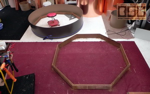
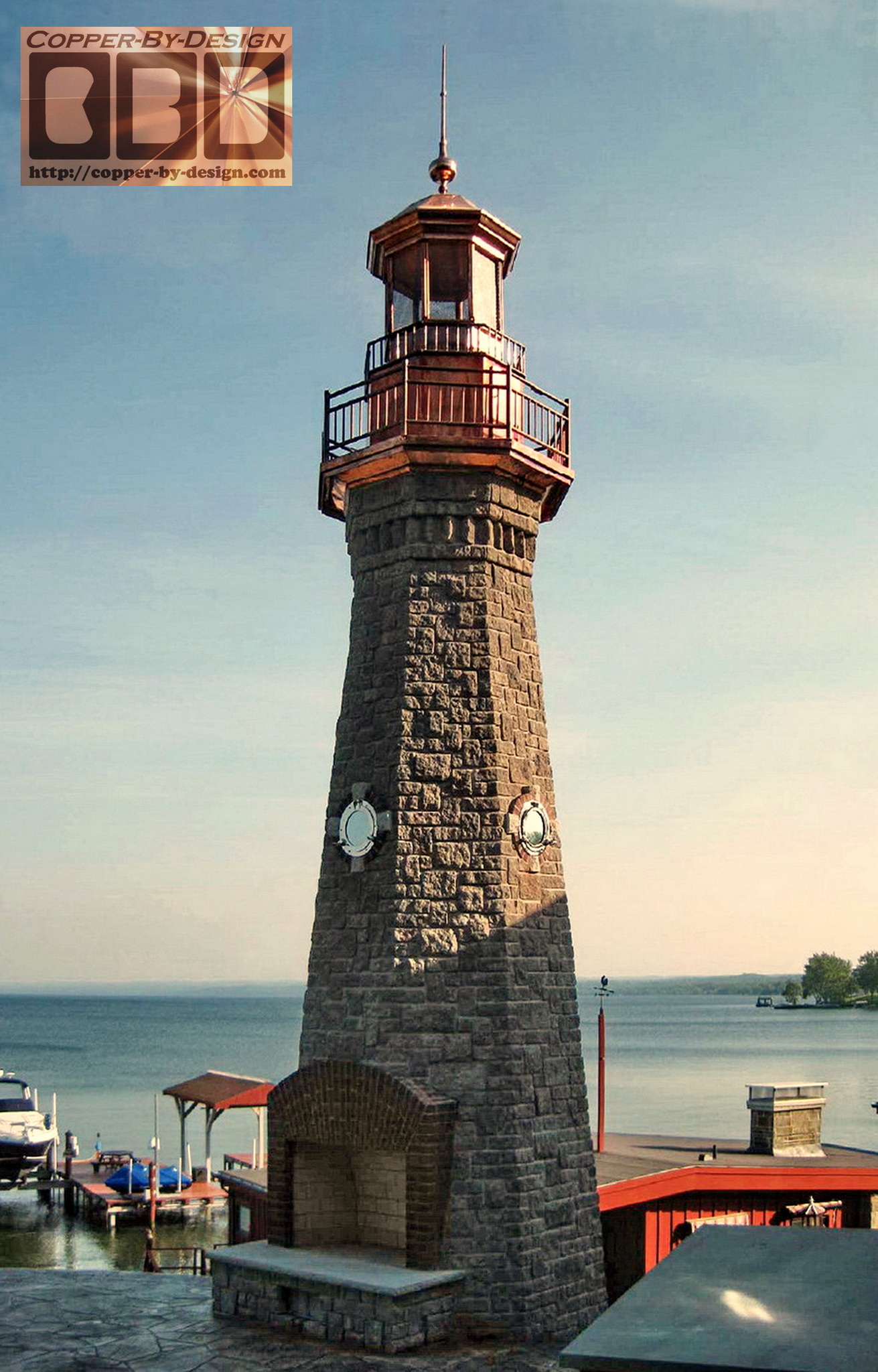
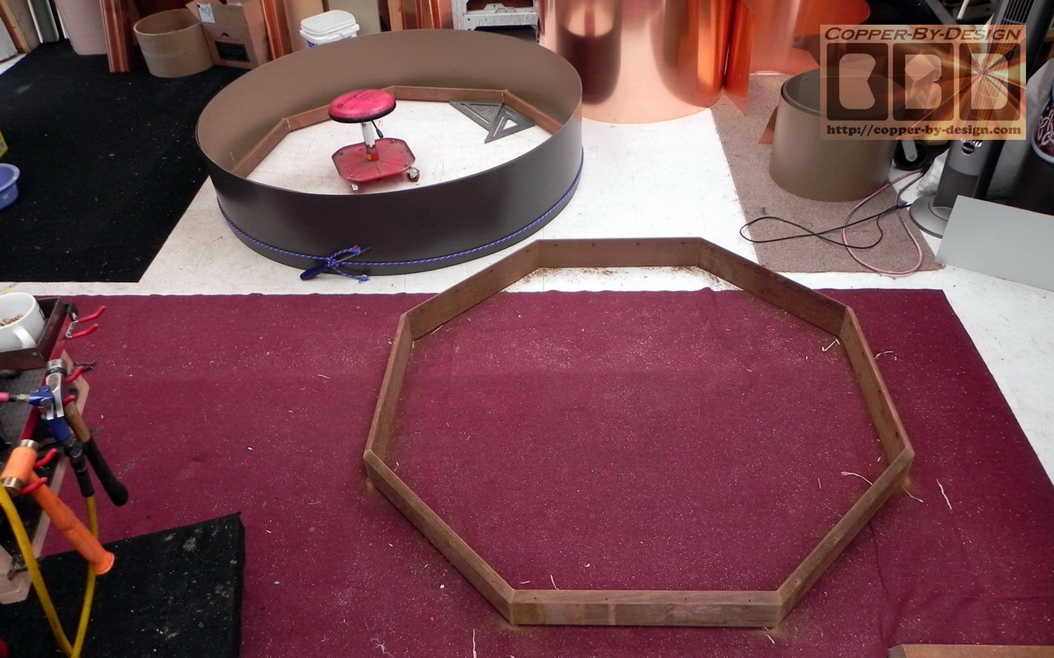
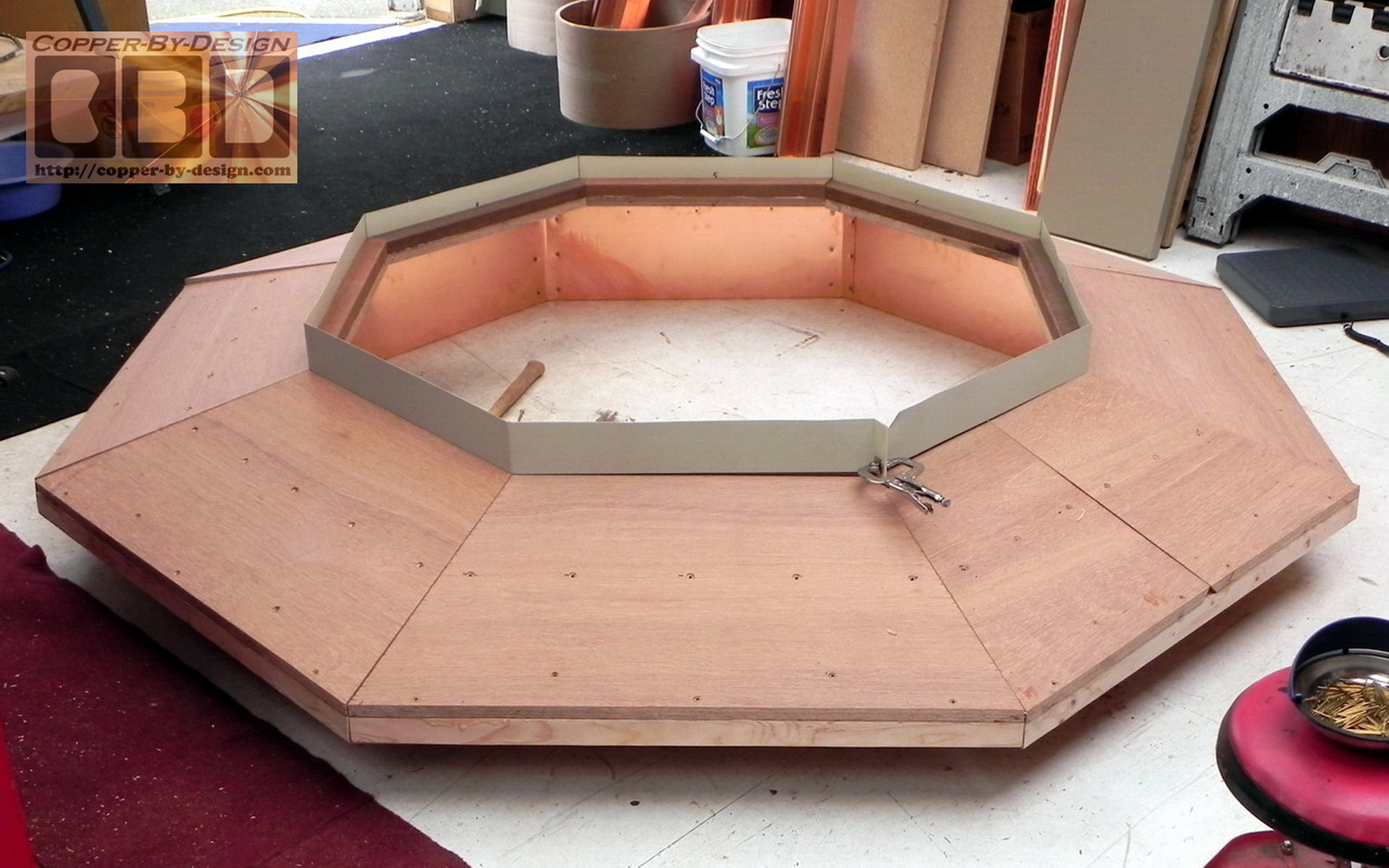
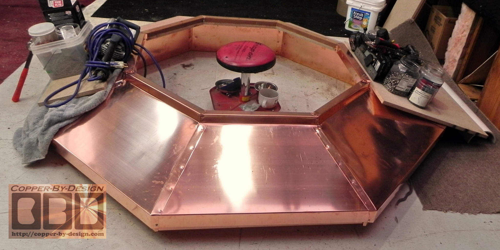
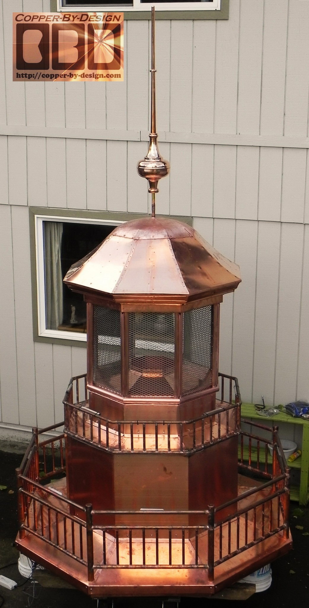
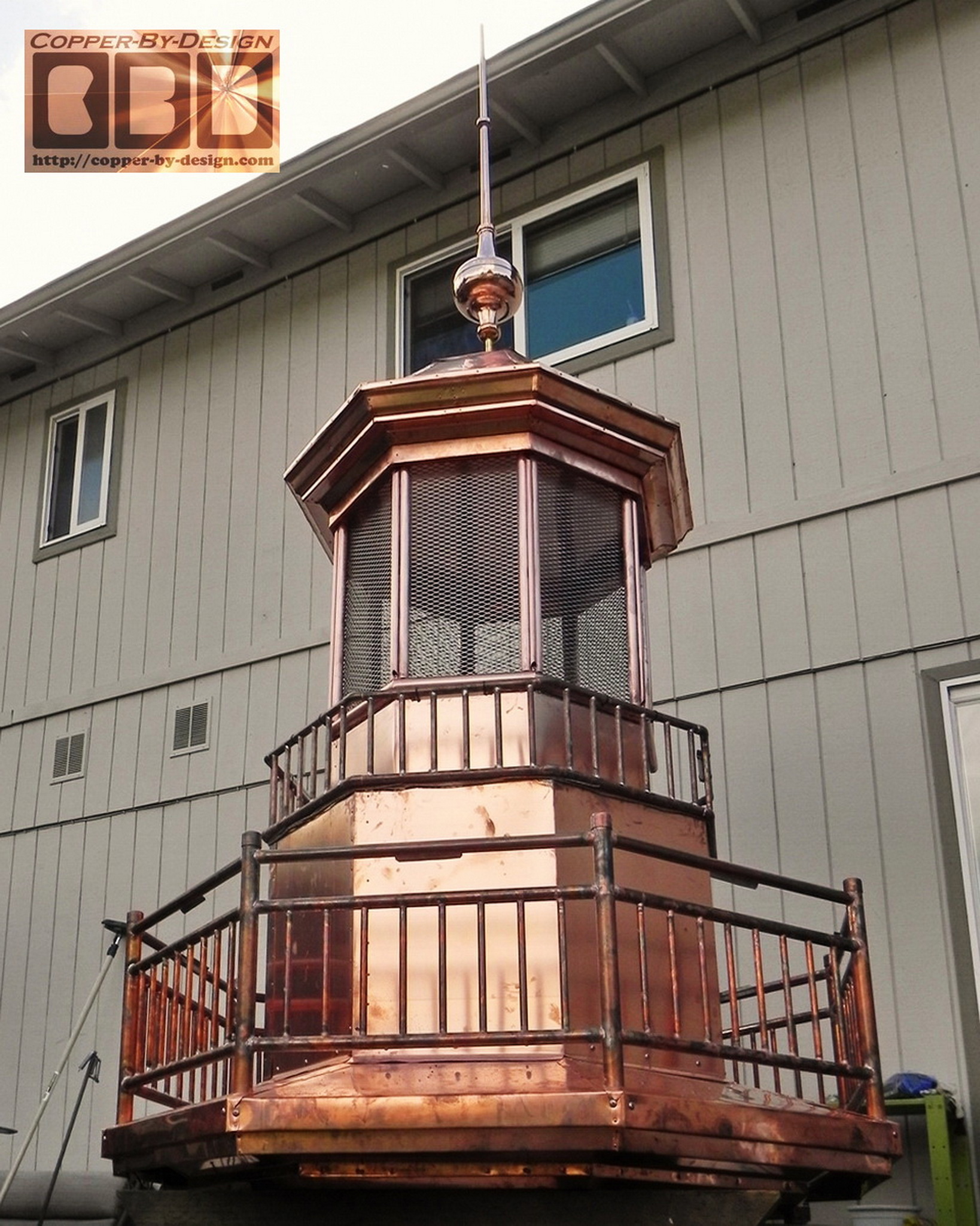
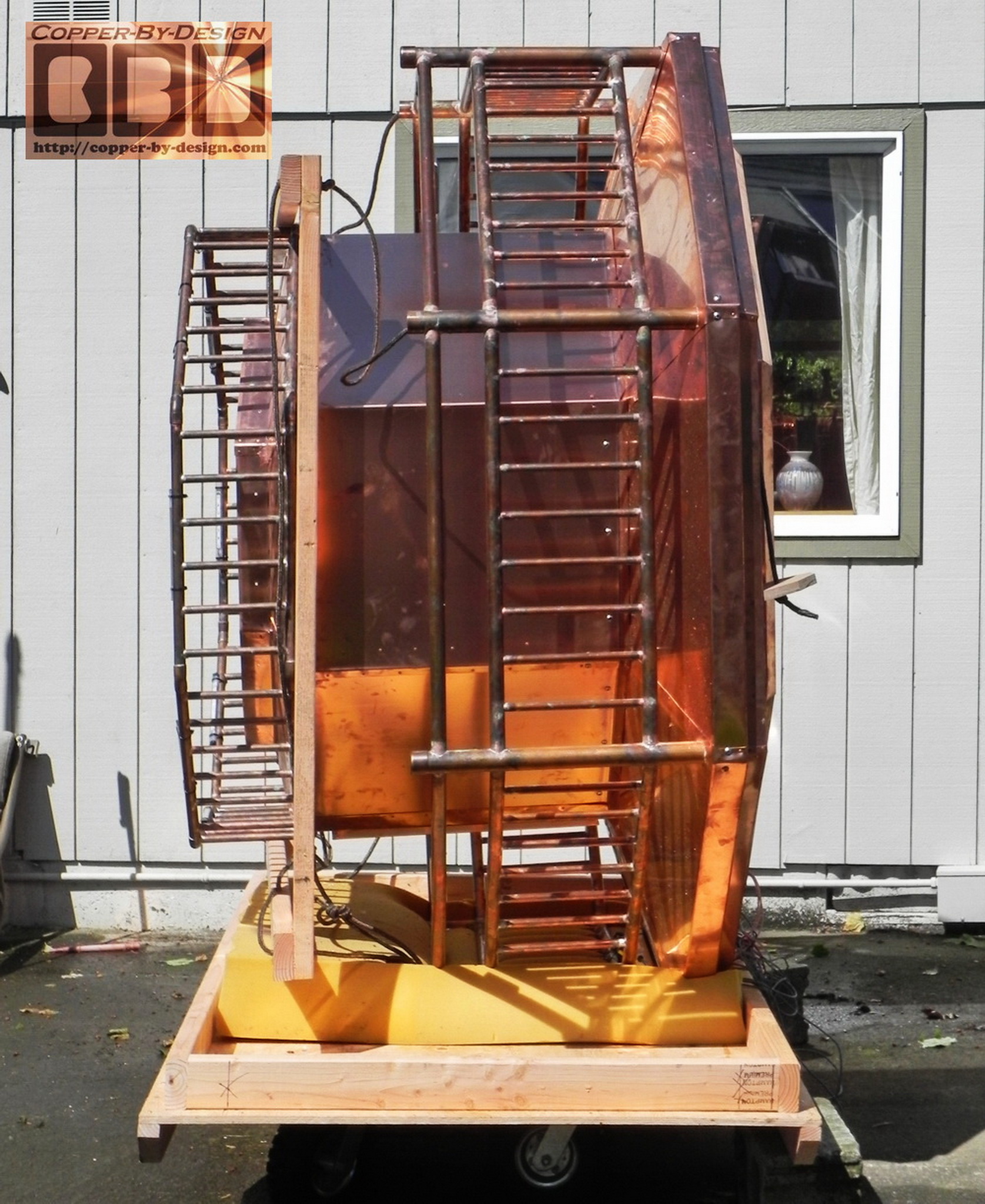
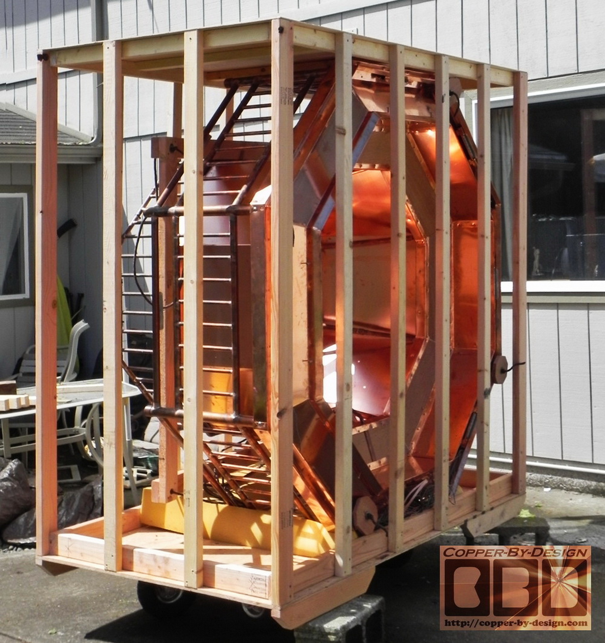
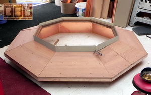
Here's the next set of photos showing the wood base coming together. The hardwood rings are bonded together and it weighs 69#. I have 6 of the 8 sheets of plywood cut which were 48#, which means they will total 64#. I decided to cut down these sheets, leaving a 44" wide hole in the middle. In these photos they are just resting over the base ring loose. They just happen to balance nicely. It was tricky to get these cut at just the right angles on all 4 edges to have the right slope.

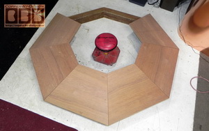
The bottom ring is glued together with the Gorilla Glue. 
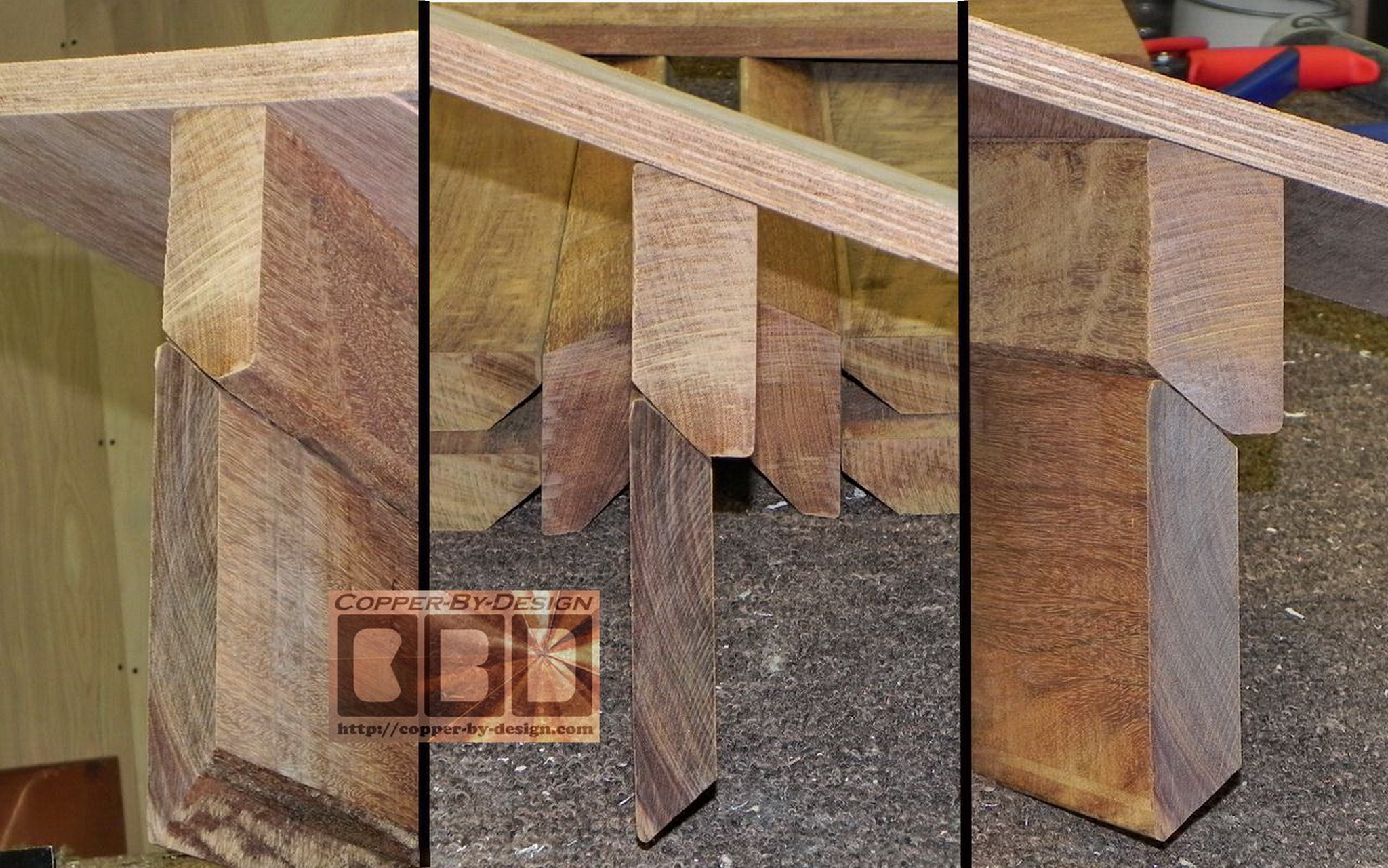
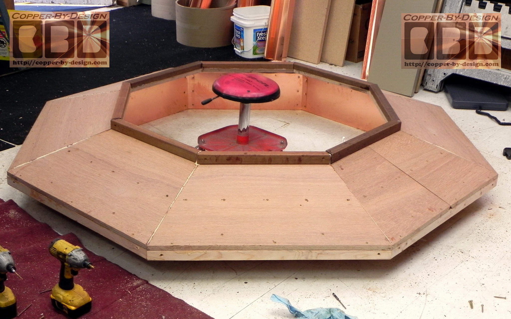
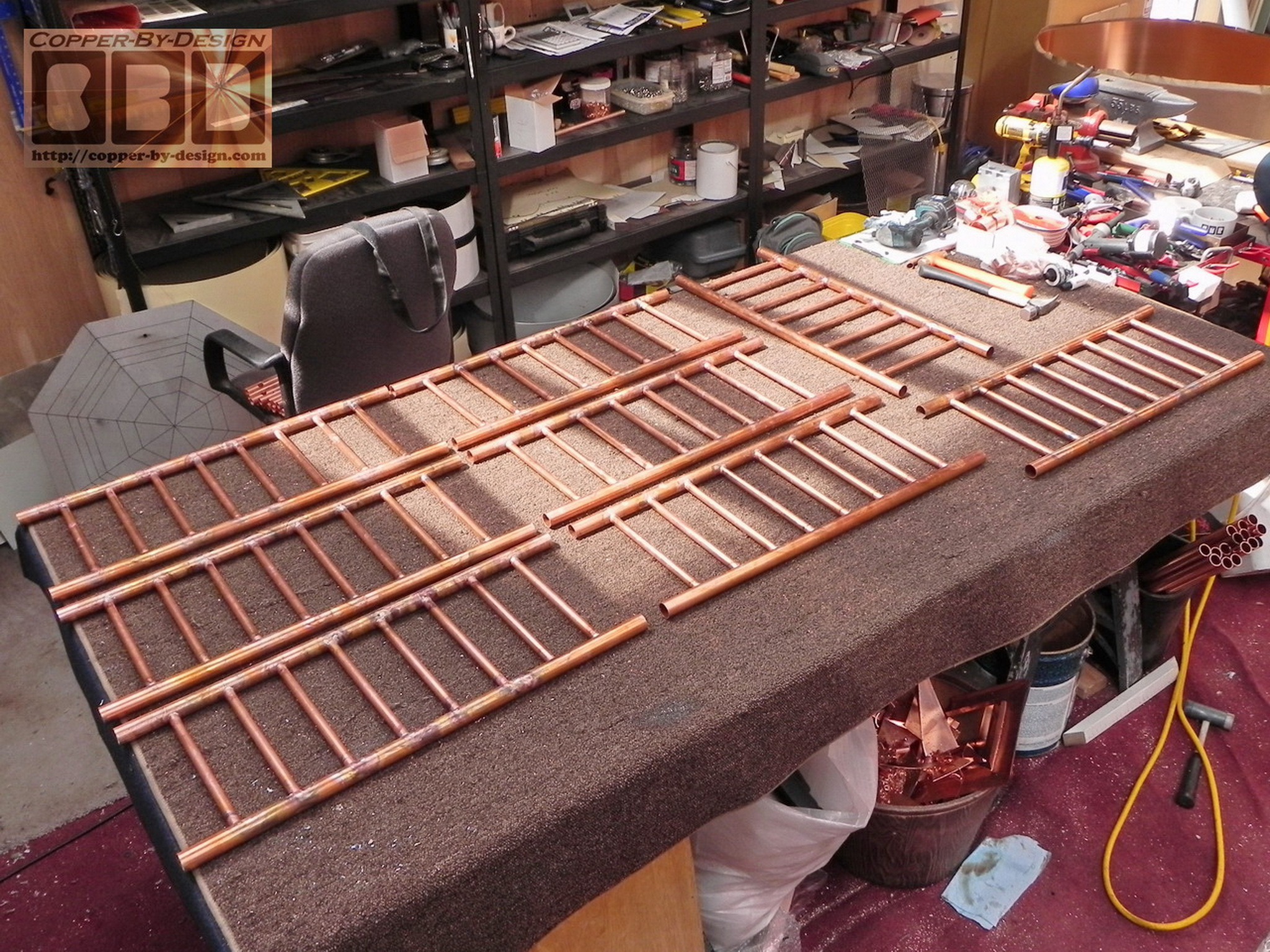
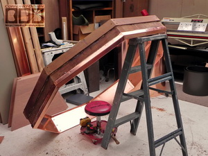
I also cut the 8 piece set of Ipe 2x4 boards at a slightly less ISW than the lower ring to more tightly hug the stone work. 
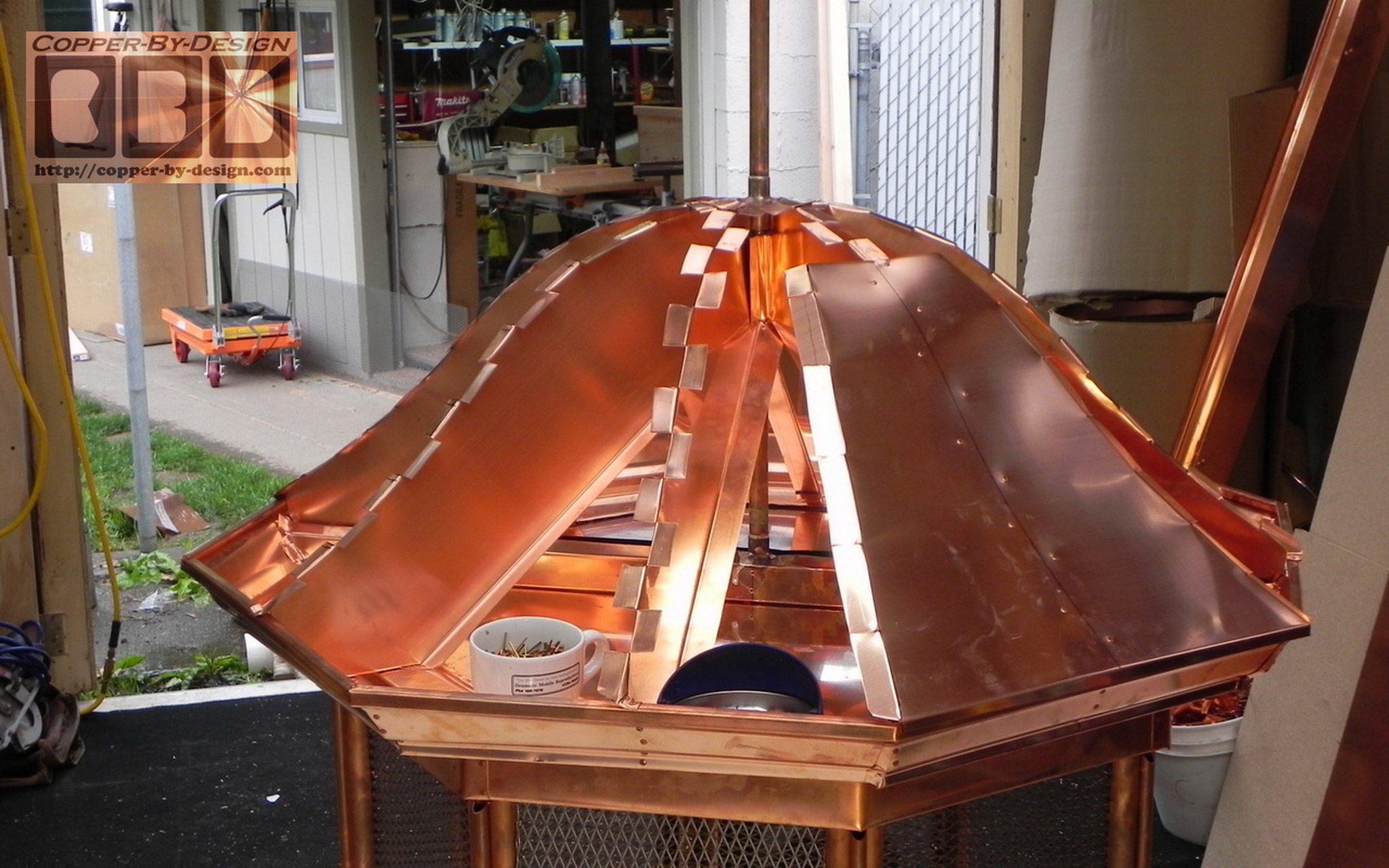
I angle cut the top edge to a 18.5 degree angle for a 4/12 pitch for the catwalk floor. The under side is trimmed to the same 45 degree angle to match the top edge of the lower ring. After I 
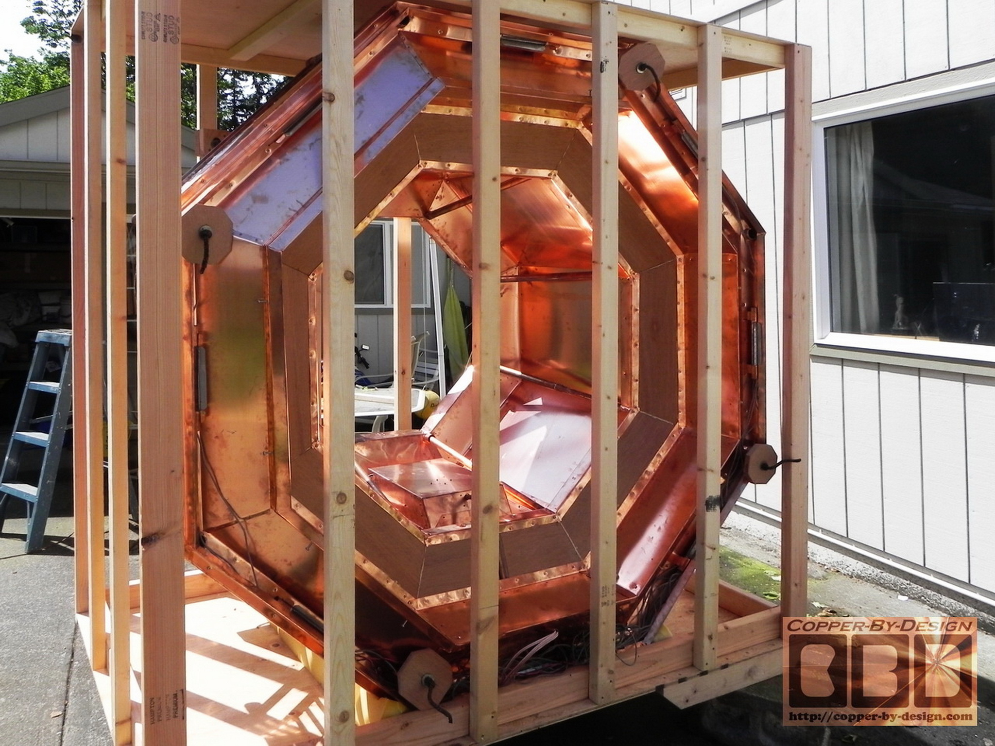
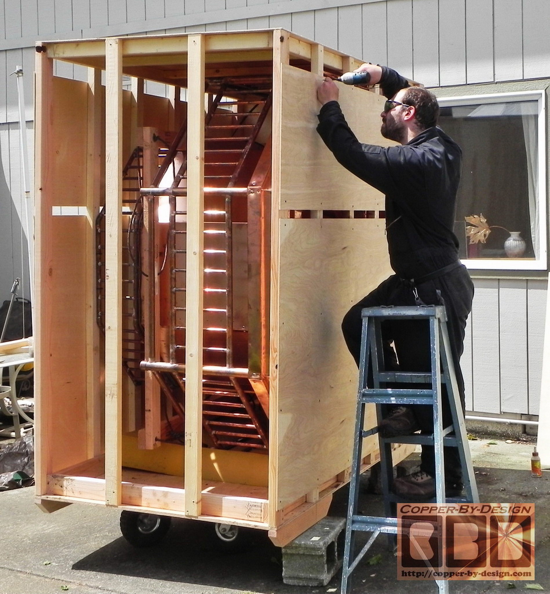
had all this glued together I covered it with 3/4" marine grade hardwood plywood to rest over the stonework and be the support under the catwalk. It will be attached to the top angle cut of the 2x4 ring with glue and screws, then covered 
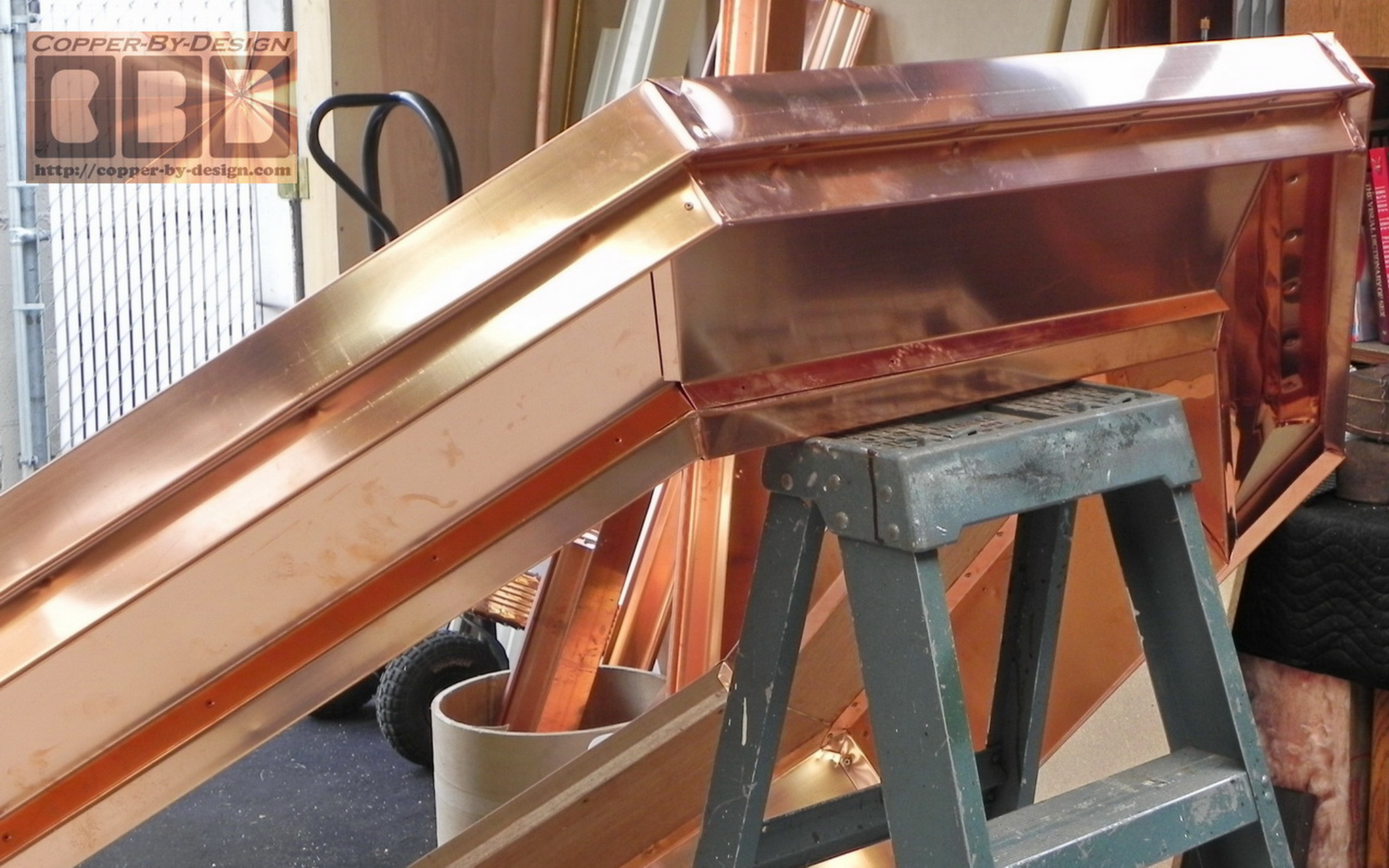
with the 20oz copper sheets.
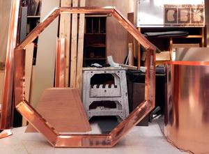
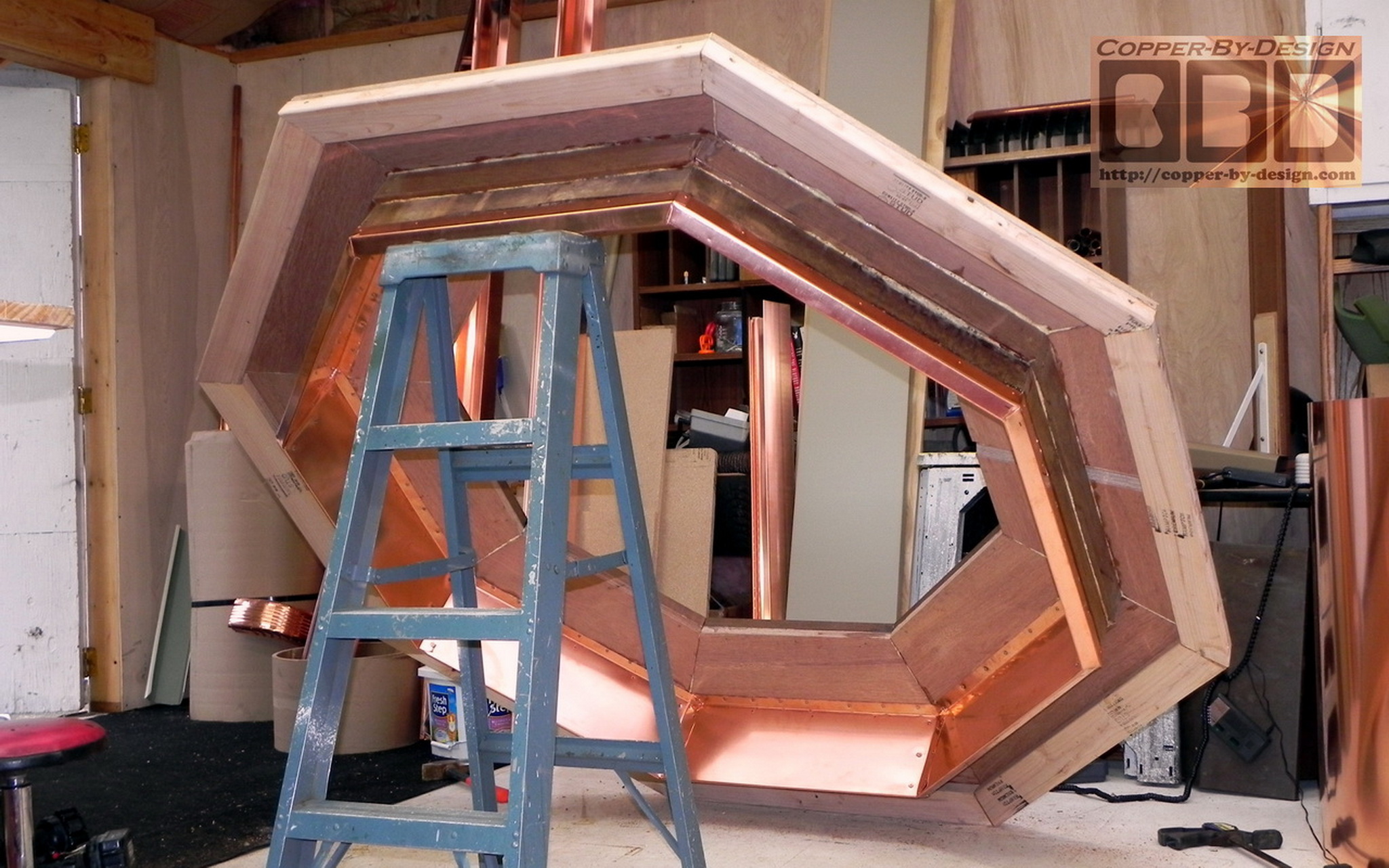
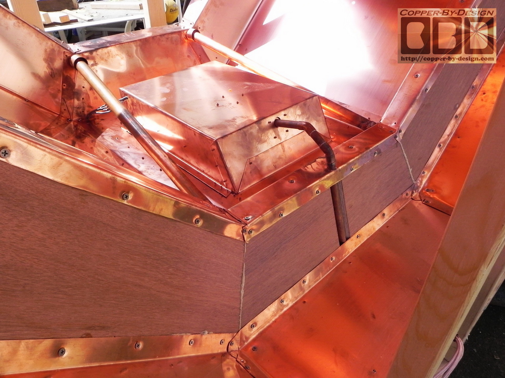
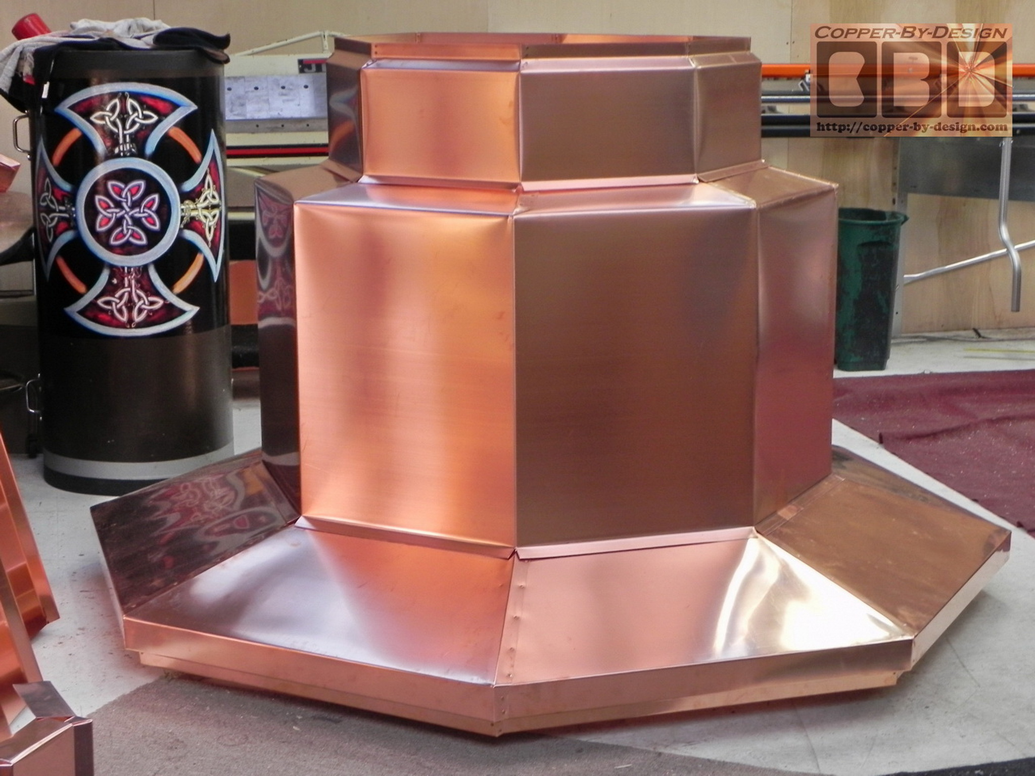
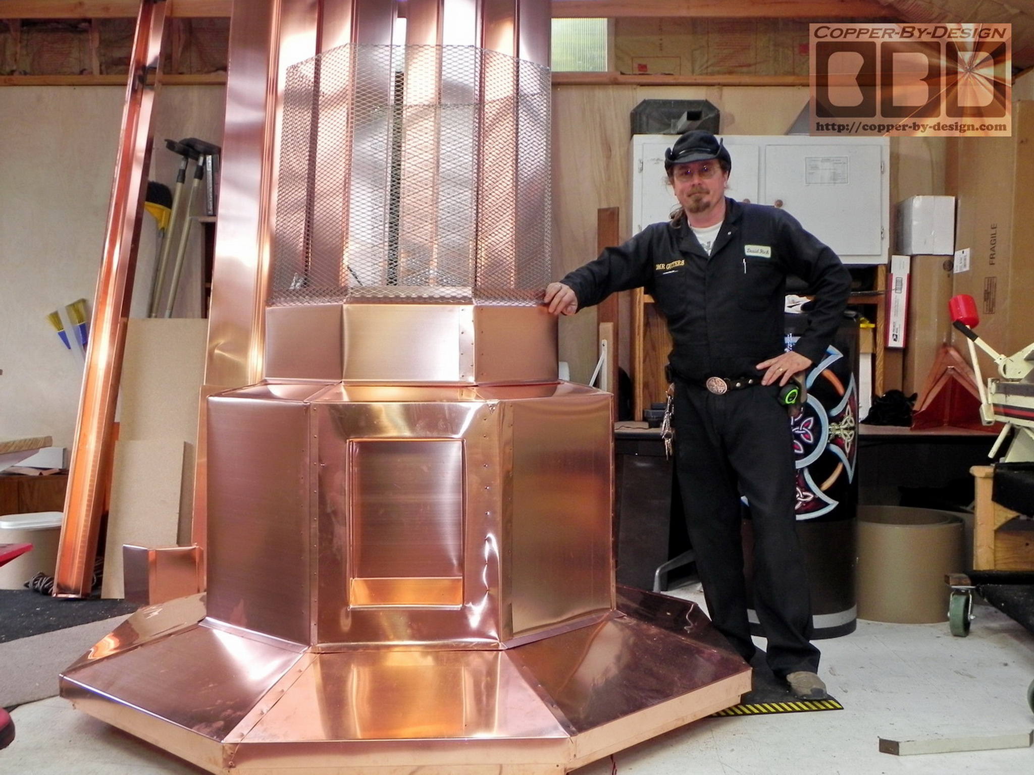
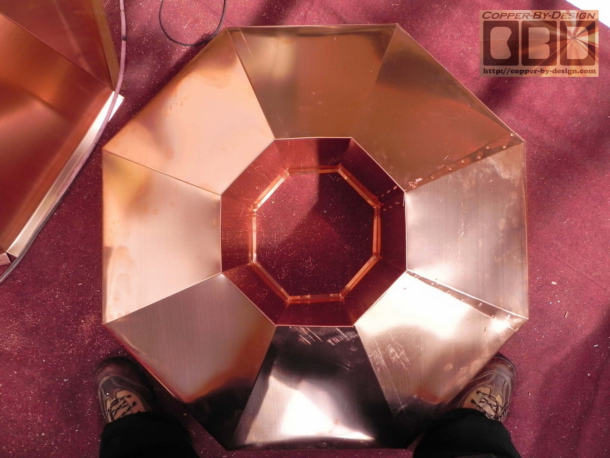
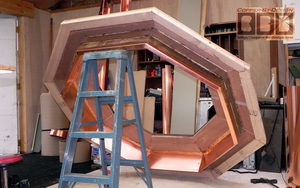
The upper and lower ring will not need to be screwed together at the corners because it has this 
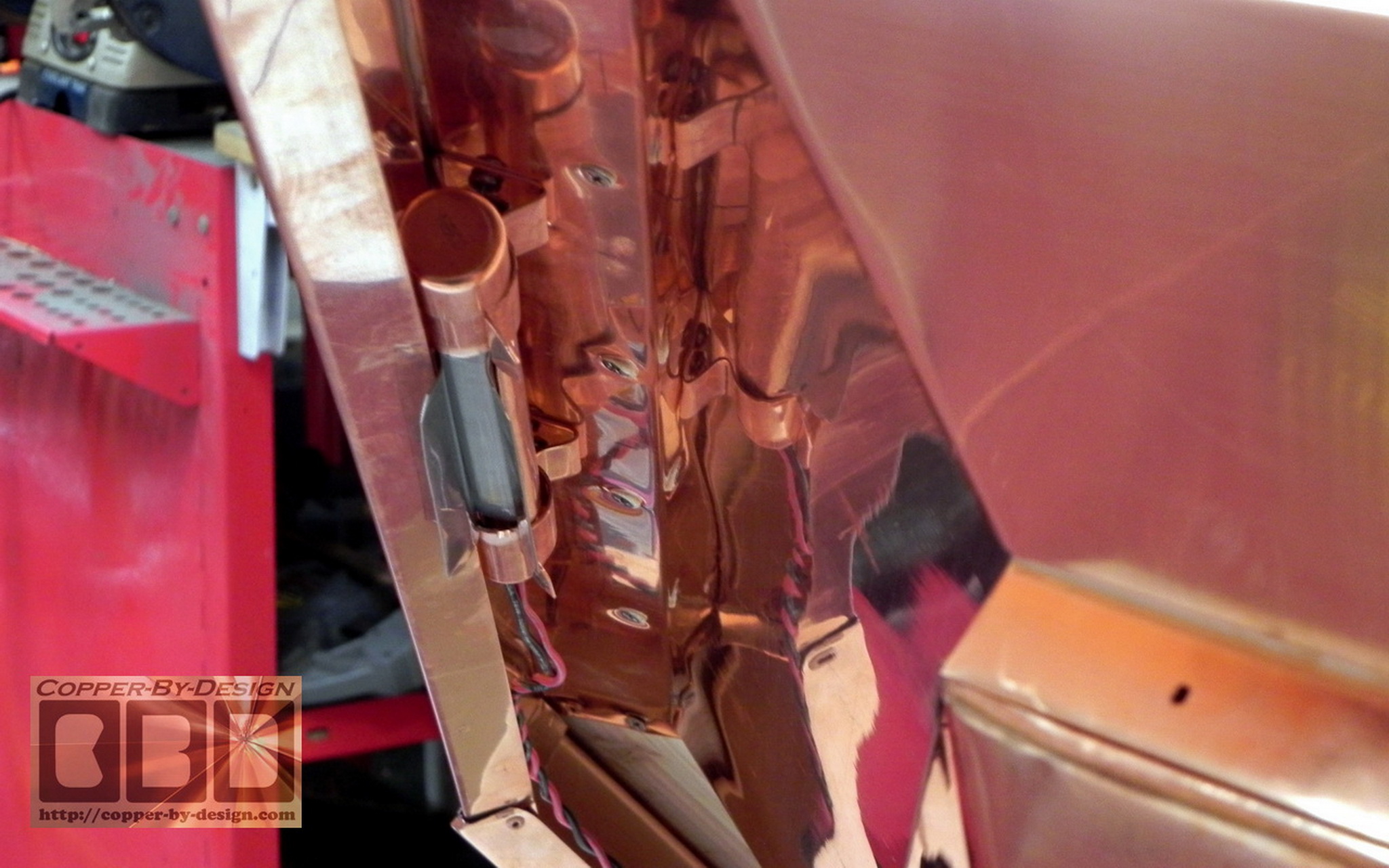
copper sheet metal inner liner between the wood and the stonework. That sheet metal with form the rigid connection. I 
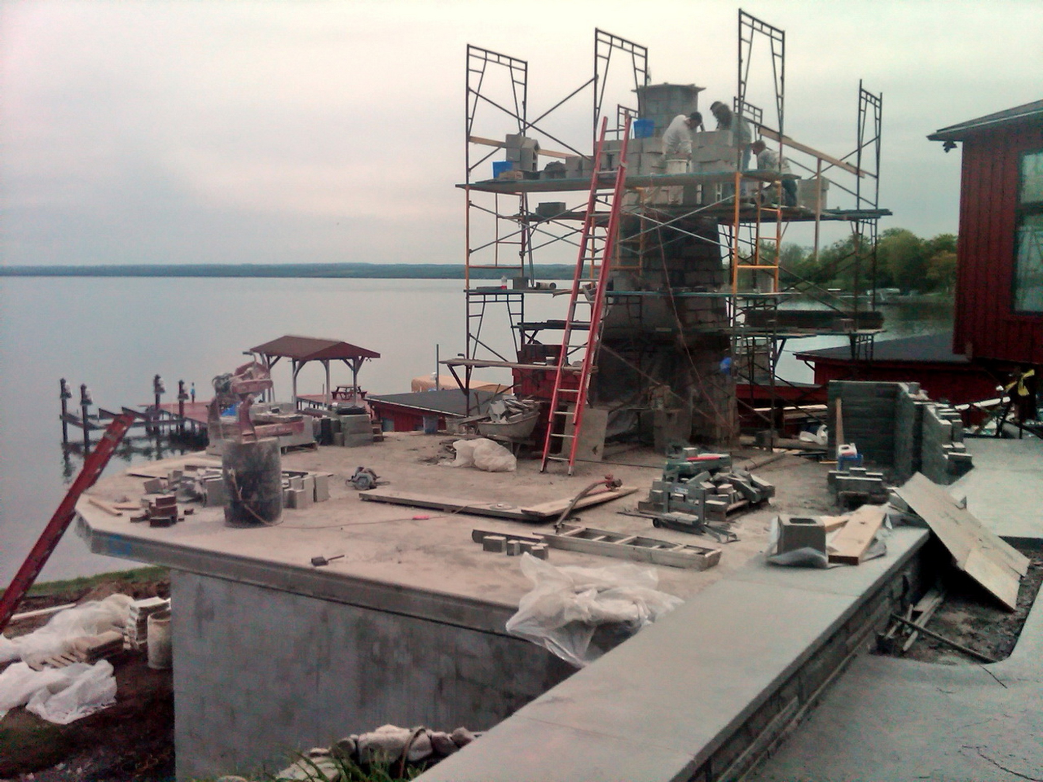
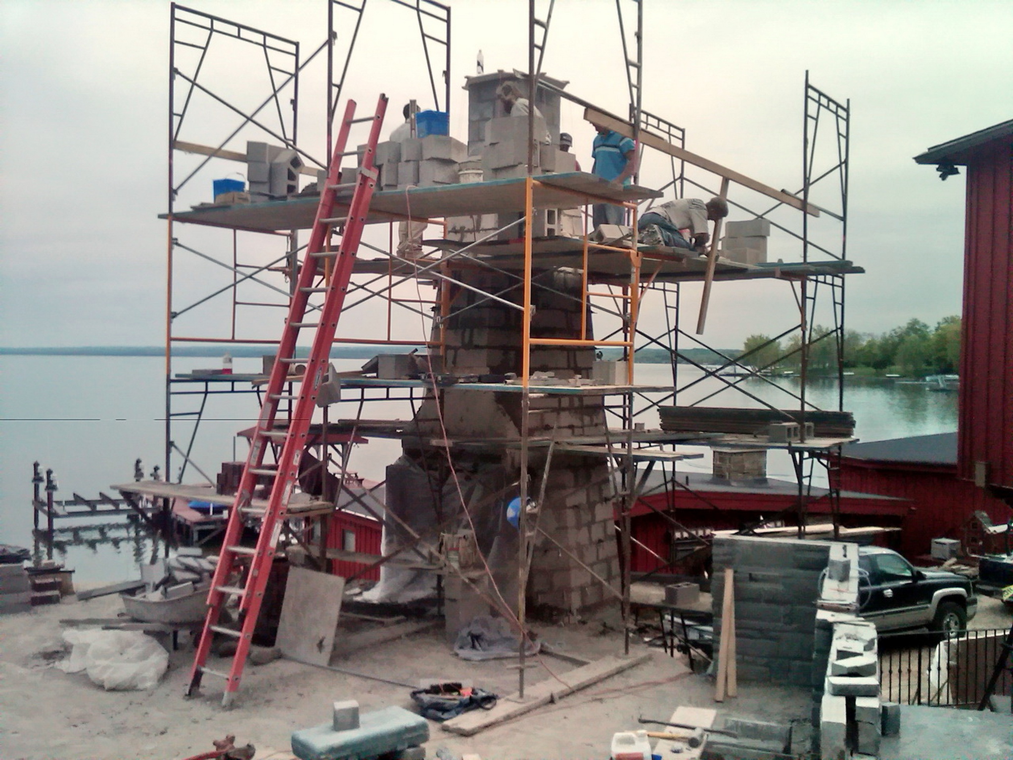
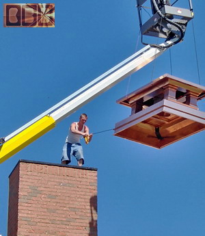
instructed them how there in New York the template frame they will need to build for the top outer ring of the stone work needs be made from a pair of 2x8 lumber 10' long cut into 8 pieces with a 22.5 degree angle cut on the ends 24.25" apart ISW. The OSW would be 25.5", but that should not be relevant to this.

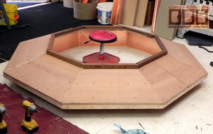
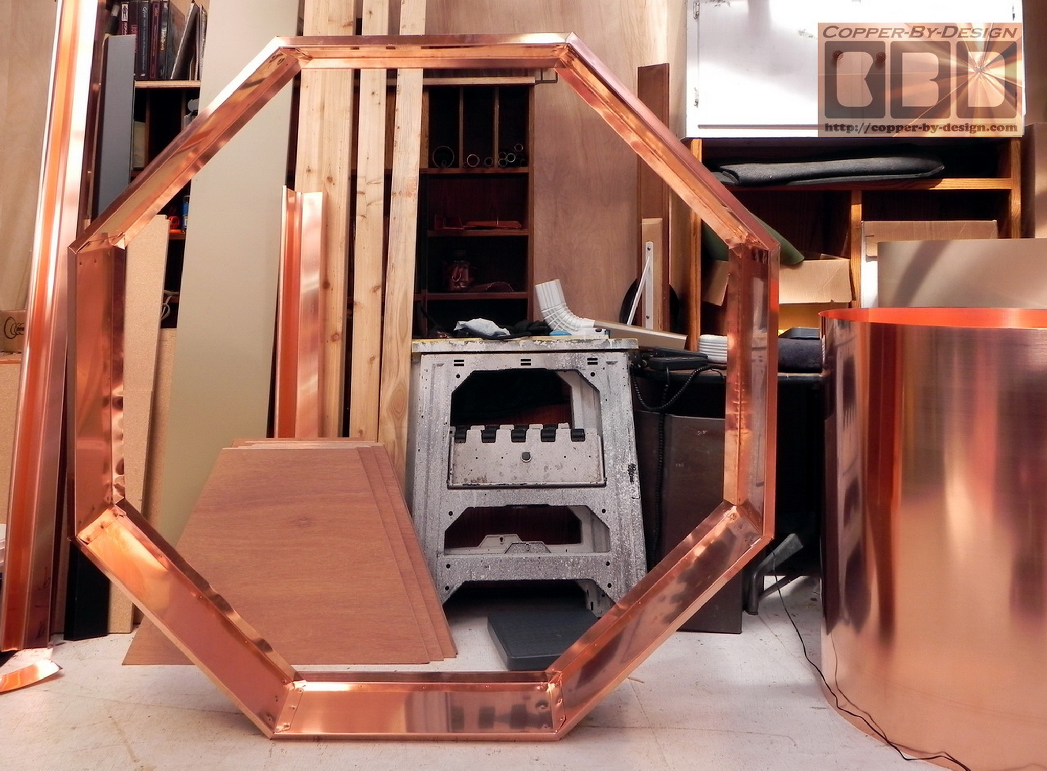
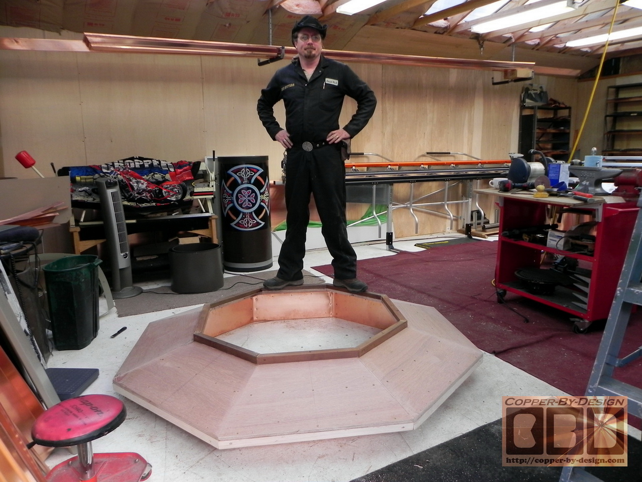
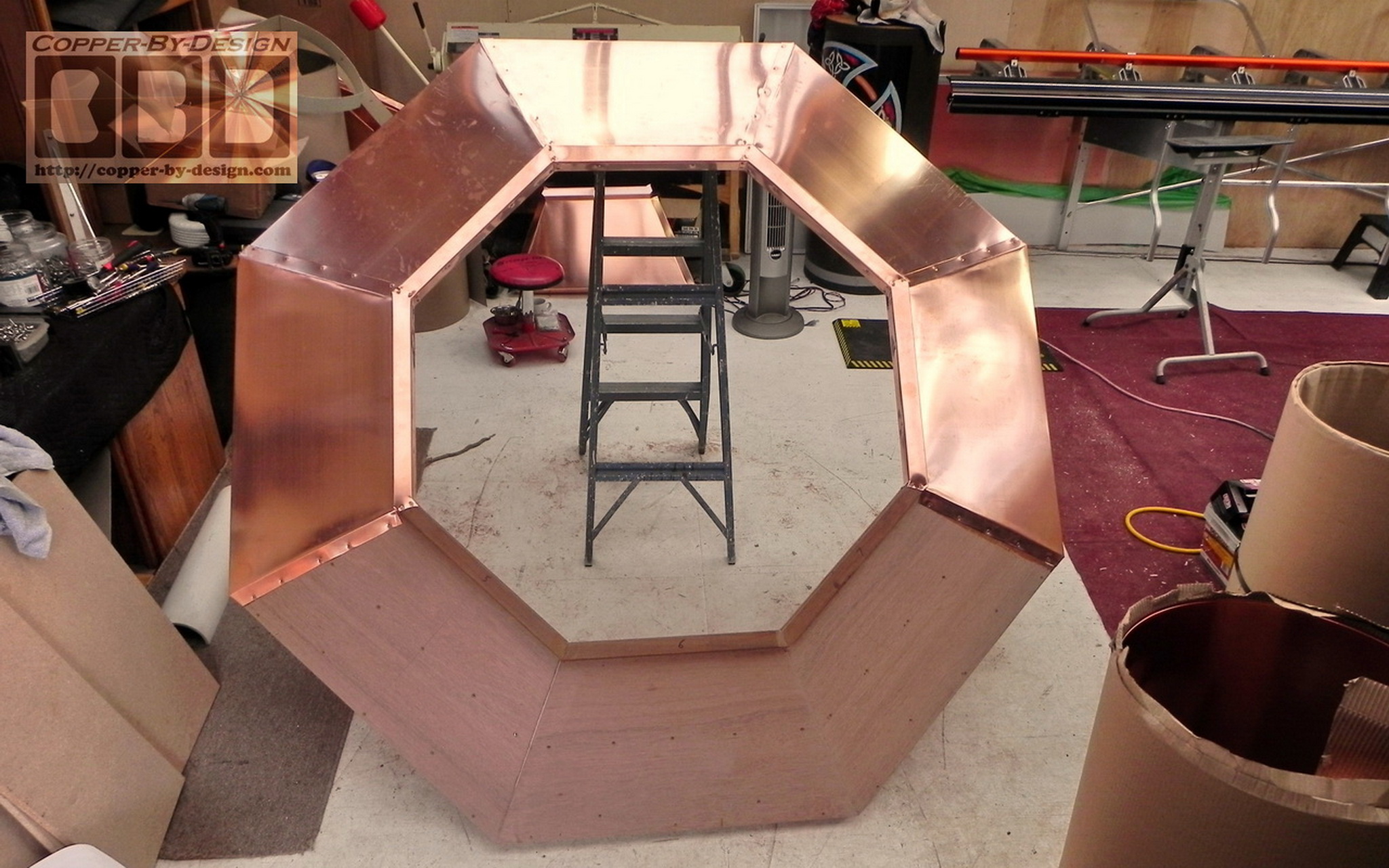
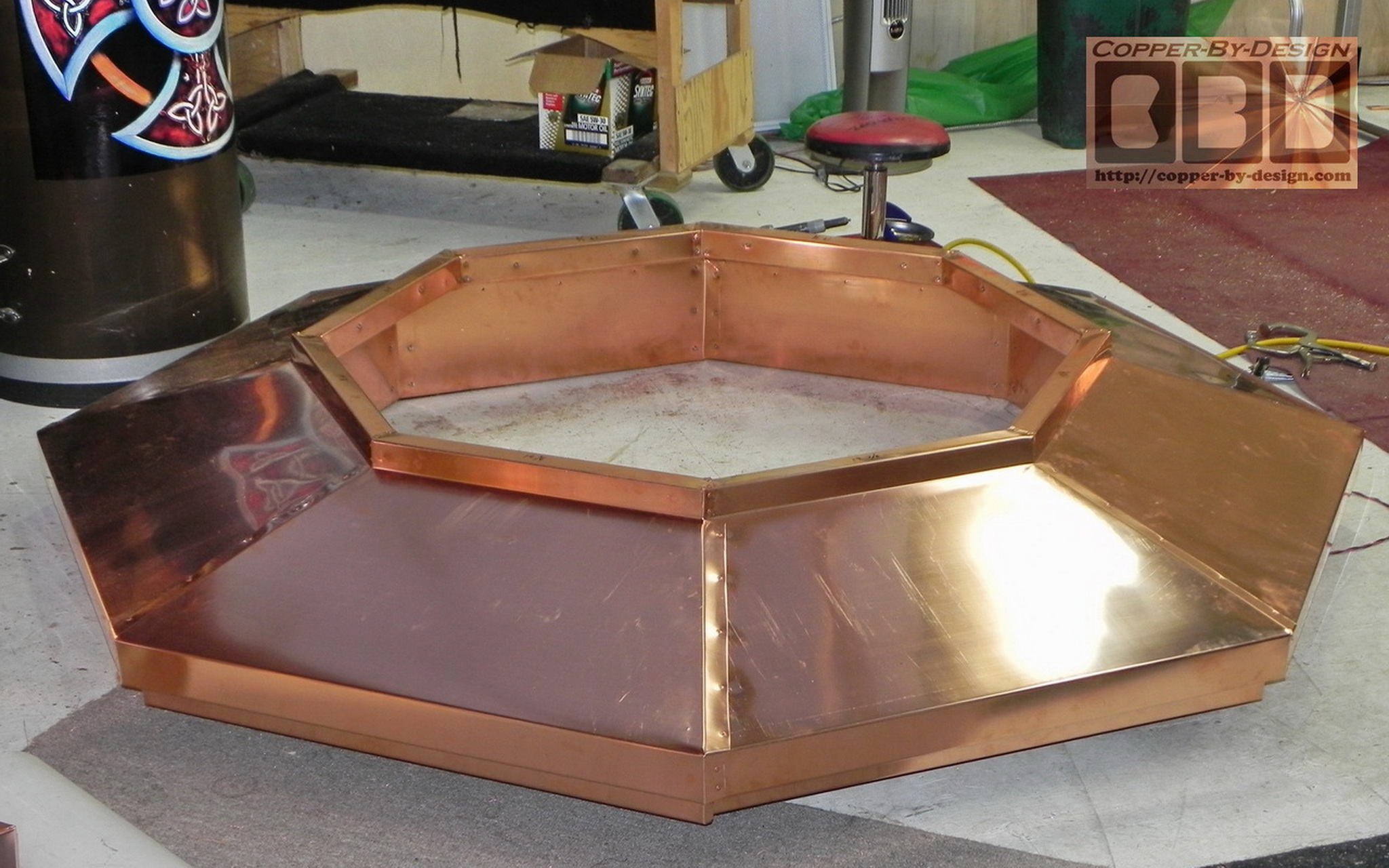
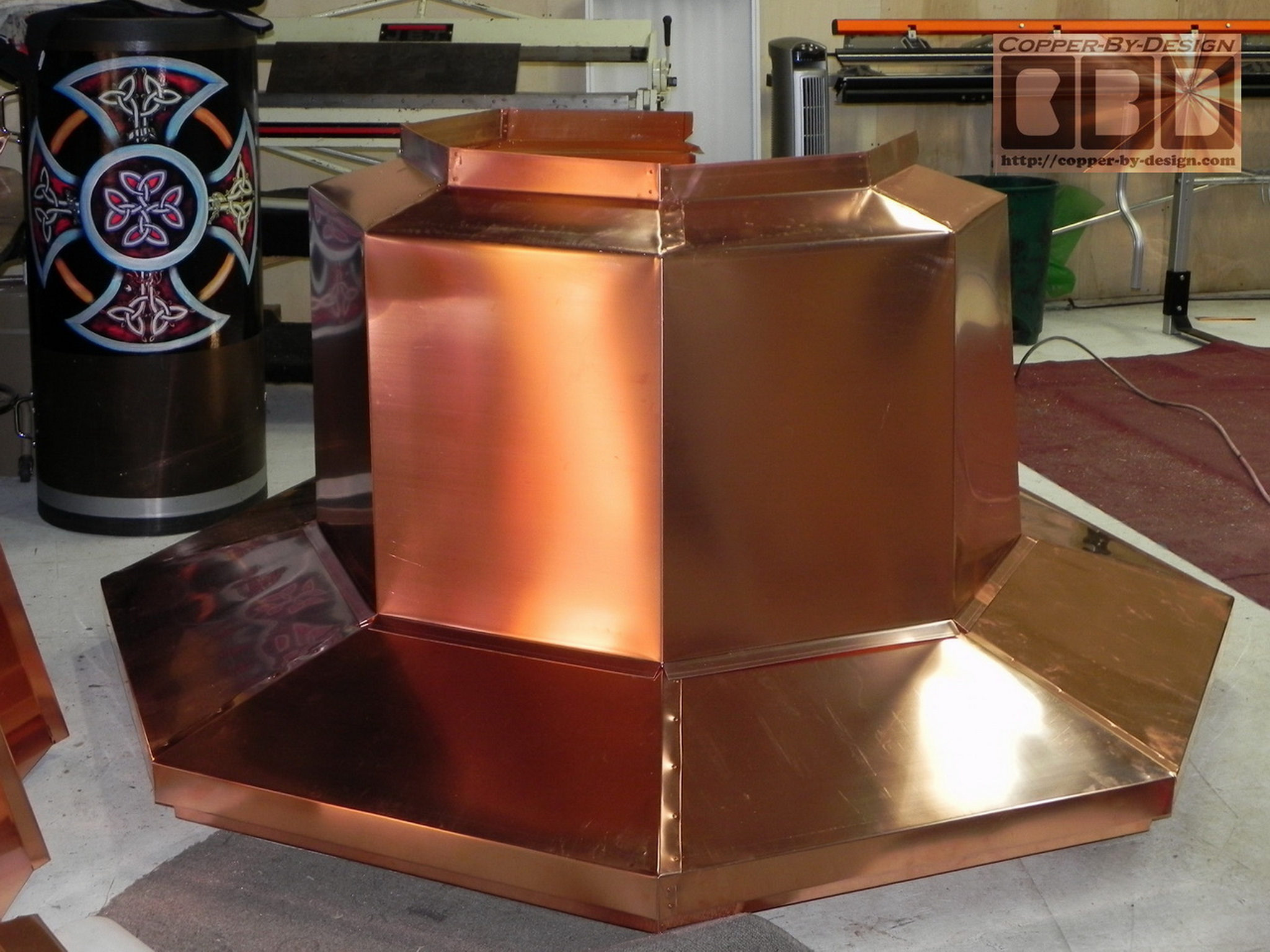
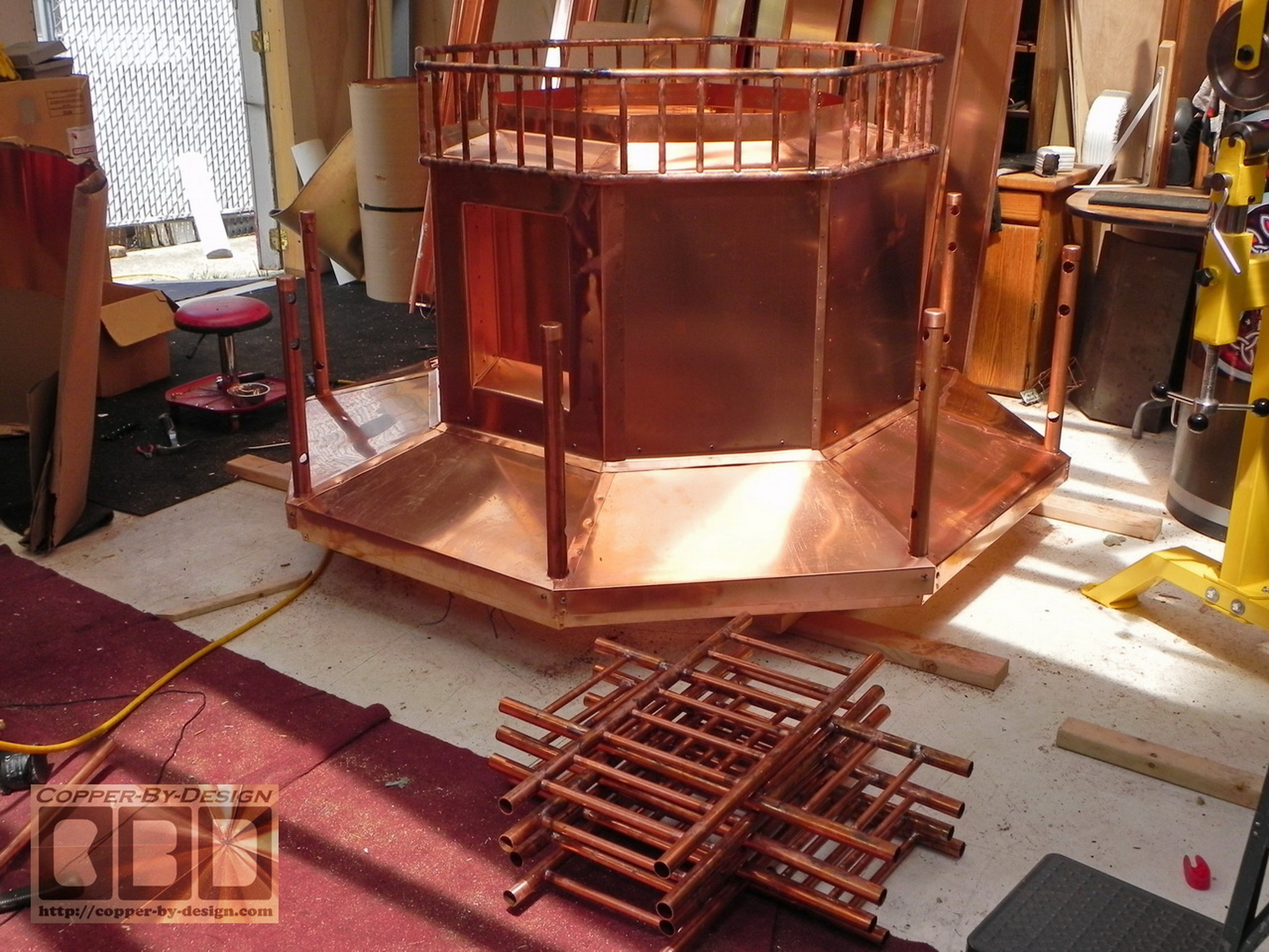
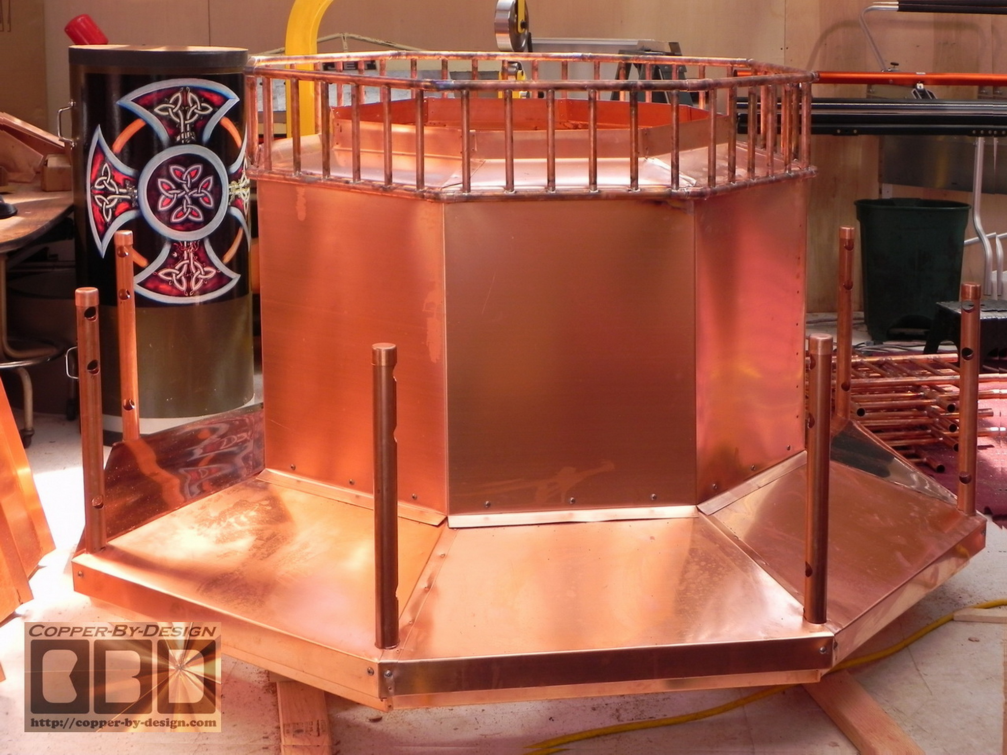
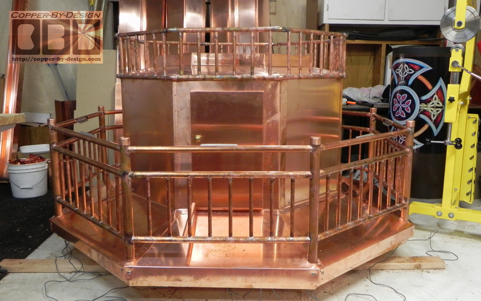
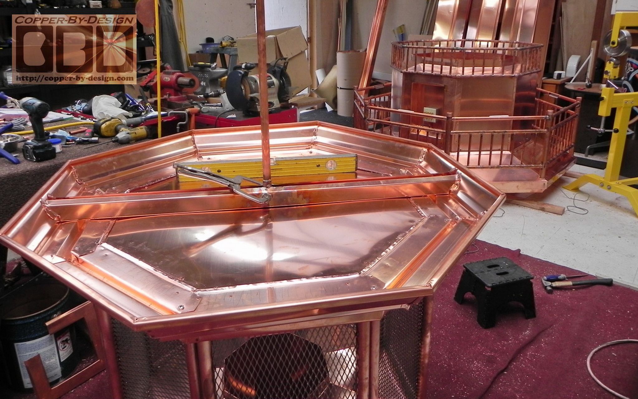
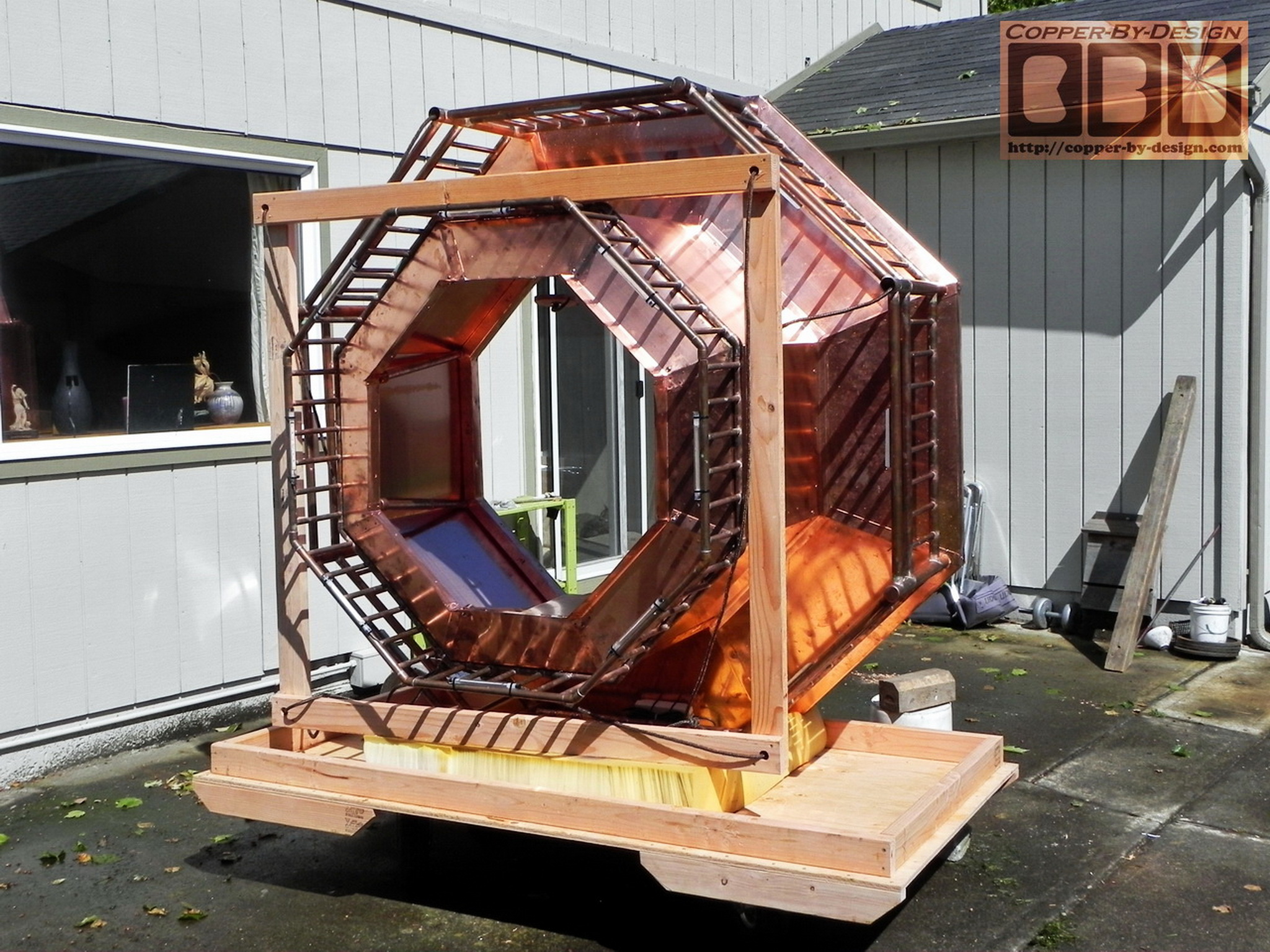
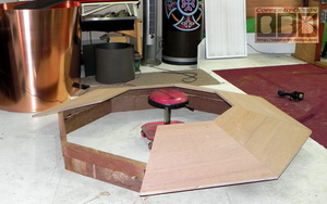
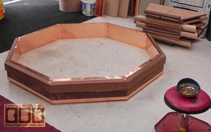
Here's the third set of photos I sent the client showing the wood base getting finished. After I cut down the plywood with the inner and outer support boards weighs 89.5#. This is 2 weeks of work to collect parts and construct this 78" wide base/skirt and catwalk floor in 158.5# of ipe hardwood and 3/4" marine grade plywood. The lower rim is lined inside with 24# of copper attached with expanding Gorilla Glue, 64 long rivets, and 120 stainless steel screws already. This is the tedious part of the fabrication, but very important to get it just right and strong. There does not seem to be any flex to it at this point, and it will get even stronger as I add more metal.

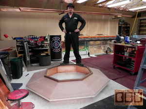
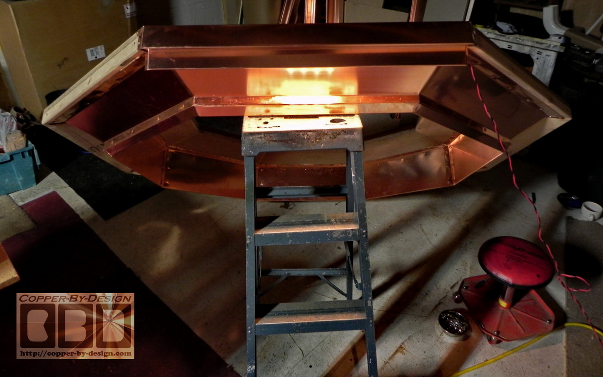
As you can see this octagonal ring is strong enough for me stand on top of it and felt quite solid under me.

.

Part 3 - Covering the Wood Base w/Copper

The catwalk has a 18.5 degree angel to shed the rain and debris. I covered it with copper sheets and made an angled soffit underneath with these brackets for the LED lights mounted under the catwalk to shine down. I had receive the transformer for the lights from the lighting guy with the 4 bulb light strand. I did a test late this evening and they definitely will not be too bright. It was not easy to try to get a good photo of it, as the camera keeps waning to make the scene brighter than it looks to the eye. I would say each strand is maybe as bright as a 40 watt bulb or a 7 to 9 watt florescent light. They have a nice even flood effect, as opposed to a spot light with a hot spot area. Close distance they are OK, but they will not light the stone very far down under the catwalk. You'll be lucky to get much light lower than 6' below. I made a video to upload to UTube to show the clients to give them a better idea how it would look.

I cut out 4 of the catwalk covers that took up an entire sheet of copper. I had them held down with weights to hold it tight while the glue sets. I made all 8 eave pieces, but I was only able to install half of them for now. I put each alternating piece on so I can still get in there to run the wiring for the lights. One panel was temporarily added just to get a lighting photo.

.

Part 4 - Setting Up The Lighting

I spent most of today working on the underside of the base after propping it up again to double check the inside measurement for the Contractor Guy. Before setting it back down on the floor I wanted to figure out the underside lighting. I made some brackets with 32oz copper. I tried to use some 48oz, but it was too stiff and would not flex enough. I also cut all 8 pipes 10" long to mount the light in and allow them to rotate the angle of the light. I made some SS shields for reflectors that hug the light strand and help hold it securely in place. These light fixtures are designed so they can be rotated for the best angle.

I After trying different things I decided it would not be best to hide the wiring inside the eave. I just laid it in the outer rim channel in case it needs servicing or you want the wiring changed later on. The video still seems a little brighter than it seemed in person. I have a single bulb LED desk lamp that seems to put out more light than this set of 4 bulb light fixtures. I had two of the lights mounted under the rim and held one to move around over it. Other than these it was completely dark in the shop. For the next test I'll have the base propped up off the floor a foot or so to get a little better idea.

.

Part 5 - Building the Mid-Chamber

Here is the mid chamber over this base. It is made from a full sheet of thicker 32oz copper 3' X 10' long to make the first 6 sides. The vertical sides are just 26" tall.


I had to make this wiring control box in one of the sides. Again made with very few seams and designed to be water tight without the need for caulk or solder. I also needed to add these 1" copper pipes inside for added support of the exhaust head.

.

Building of the Fireplace & Chimney

These are a few shots set to me by the client showing the progress as of 5/10.

.

Part 6 - Building the Exhaust Head

 The next upper section is made. I decided to get another sheet of the 32oz copper for this section as well.

We have 7 sides of the screen cage formed from a single piece. That's all we could make with the 8' long sheet at 14" wide on each side. I made the last side removable for servicing. If they ever decide to mount a light inside like a real lighthouse this will allow for that as well.

This pan I formed inside the spark arrest screen area will drain any rain water outside than may get blown in through the screen in a windstorm. I also added a flue liner to help channel the exhaust up through to the exhaust head. These are details I had not added to the earlier lighthouse shaped chimney cap I made.

We tried it on the mid chamber to get this shot for the client. I then worked on building the crown molding for the roof.

.

Part 7 - Building the Railing

To the left is a shot showing most of the 285' of copper pipe needed for the railing and trim work after we got them all cleaned up. They had to be wiped down with lacquer thinner to remove the printing and tape gum. We cut them into 194 separate pieces, and drilled 280 holes in the larger pipes.

It took Chris all day to mark and cut 224 holes just for the vertical 1/2" pipe railing pieces on the drill press. Chris stayed here over night Friday evening to help out and all day Saturday. I work all day Sunday as well to catch up on this project that was suppose to be shipped out on the 14th, but we were not able to make that deadline. How's that for dedication?

This client wanted to be able to have it installed by Memorial Day. We managed to get it off to them on the 20th and it arrived on the morning of the 26th, so they were still able to get the lighting finished up and got it mounted by crane that 24' up off the ground.

Below shows the railing sections soldered together. Then with the corner poles mounted they were ready to get soldered in place. You'll see them finished with the 8 sets of LED lights hidden inside the top horizontal rail of the main railing.

The corner posts are made with a 1.5" copper pipe set in holes drilled through the 2.5" base. They are glued and set with large #14 SS screws and they felt remarkable sturdy.

.

Part 8 - Building the Bell Shaped Roof/Finial Support

I added this flat sheet over the screen area to close of the exhaust from going up into the roof, but more importantly so it looks good from underneath. Then I mounted the cross brace to hold the bottom of the finial support pipe in place, making sure it was vertically level before soldering and riveting it in place.

Then I made the roof support frames to hold the bell shape. After all 8 sides were attached I had used the English Wheel to shape a sheet of 32oz copper into a dome for a seamless cover over the center of the roof.

After seeing it assembled I felt the finial needed to be dropped down a few inches and I added this short piece of 1.5" pipe to make this look more substantial between the roof and the finial.

.

Part 9 - Final Assembly & Crating

After I moved it outside I did more light test late at night to show the client what it would look like in the form of a video, since it is too hard to get a still photo of this in the dark:
http://www.youtube.com/watch?v=FA3FF5vbySU
http://www.youtube.com/watch?v=buJ9qZGKOEo&feature=related

This shows the finished project outside before it gets crated up for it's long journey from the West Coast to the East Coast. As you can see it is quite substantial looking next to our 2 story house. It was over 8' tall without the finial and about 13' tall with it.


.

Click in this photo to go back to Chimney Caps main info page

.


Below is a photo of our
Better Business Bureau's
NW Business Integrity Award
for the year 1998

1999 Better Business Award

We were also a 1997 finalist for this same award. See our referral web page to see how we managed to be honored with this special award


Back to homepage
Homepage

Site Map

.

Company
Profile
Roof Caps You are here Chimney
Caps
Scuppers Gutters Shipping

Contact Info
.

.

.

.

.

.

..

.

.

.

.

 copper-by-design.com