|
This is the largest and most elaborate
copper chimney cap project I have worked on to date. This is for
Greg Besio in Hinsdale Illinois, who had a house built on the
lake in Glen Arbor, Michigan. He first contacted me 2/17/08 and we
gradually worked out this project through 60 some e-mails along
with
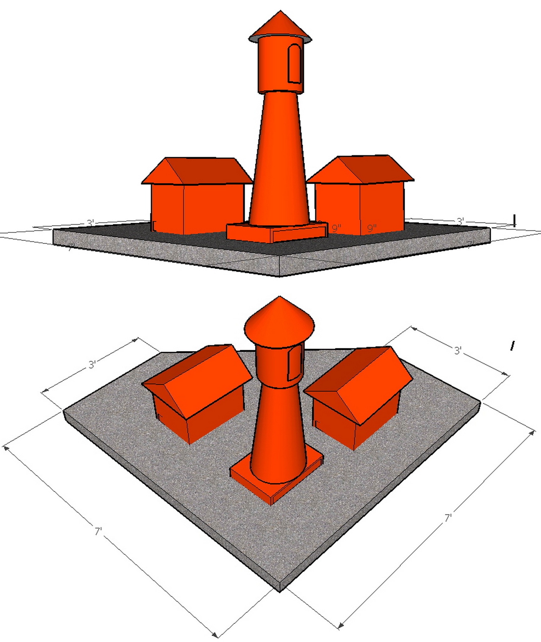
several photos and finally to this diagram on the right.
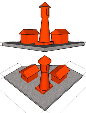 
I had to explain how his first diagram (shown on the left)
idea would
not have worked out. Mainly since it would not have allowed for a
sufficient exhaust flow. He has 3 flues in a single chimney and
he was originally thinking of covering each one separately with
this taller one resembling a lighthouse. He also realized this would
be too small to be recognizable as a lighthouse shape, so he decided to have me re-quote this to make one larger
lighthouse shaped chimney cap to cover all 3 flues and this is
what we came up with from our collaborative efforts.
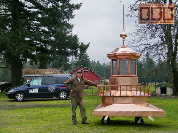
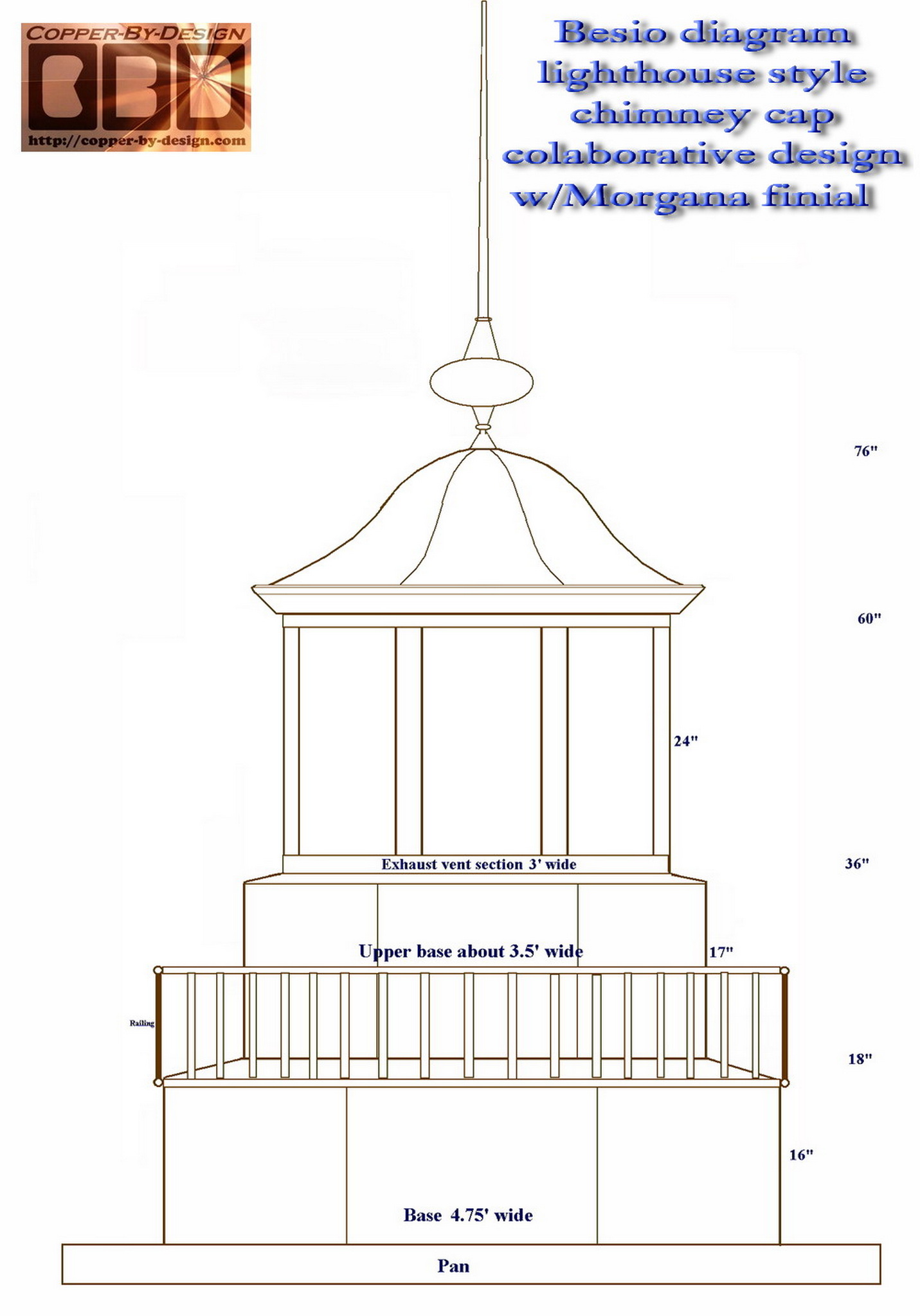
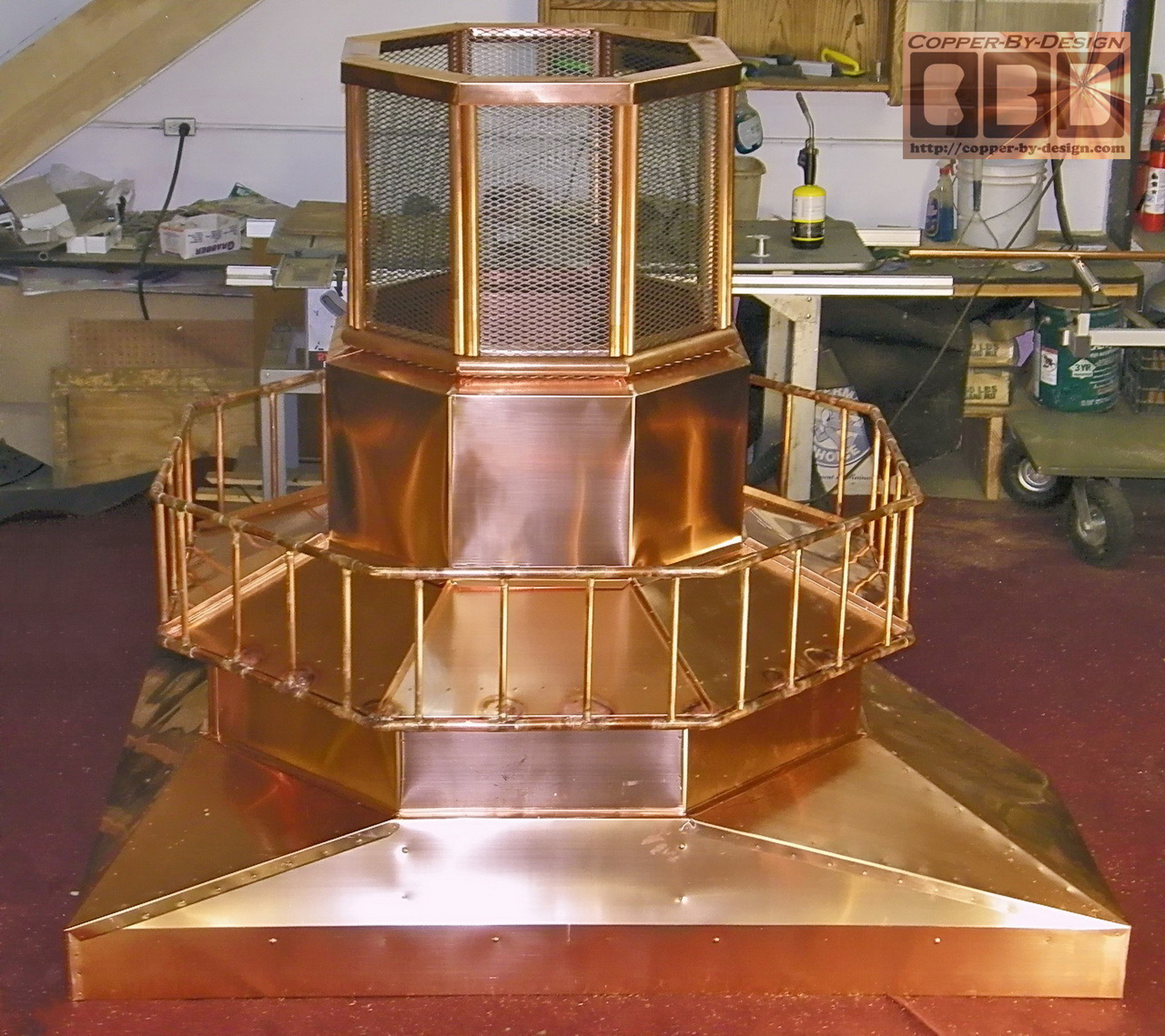
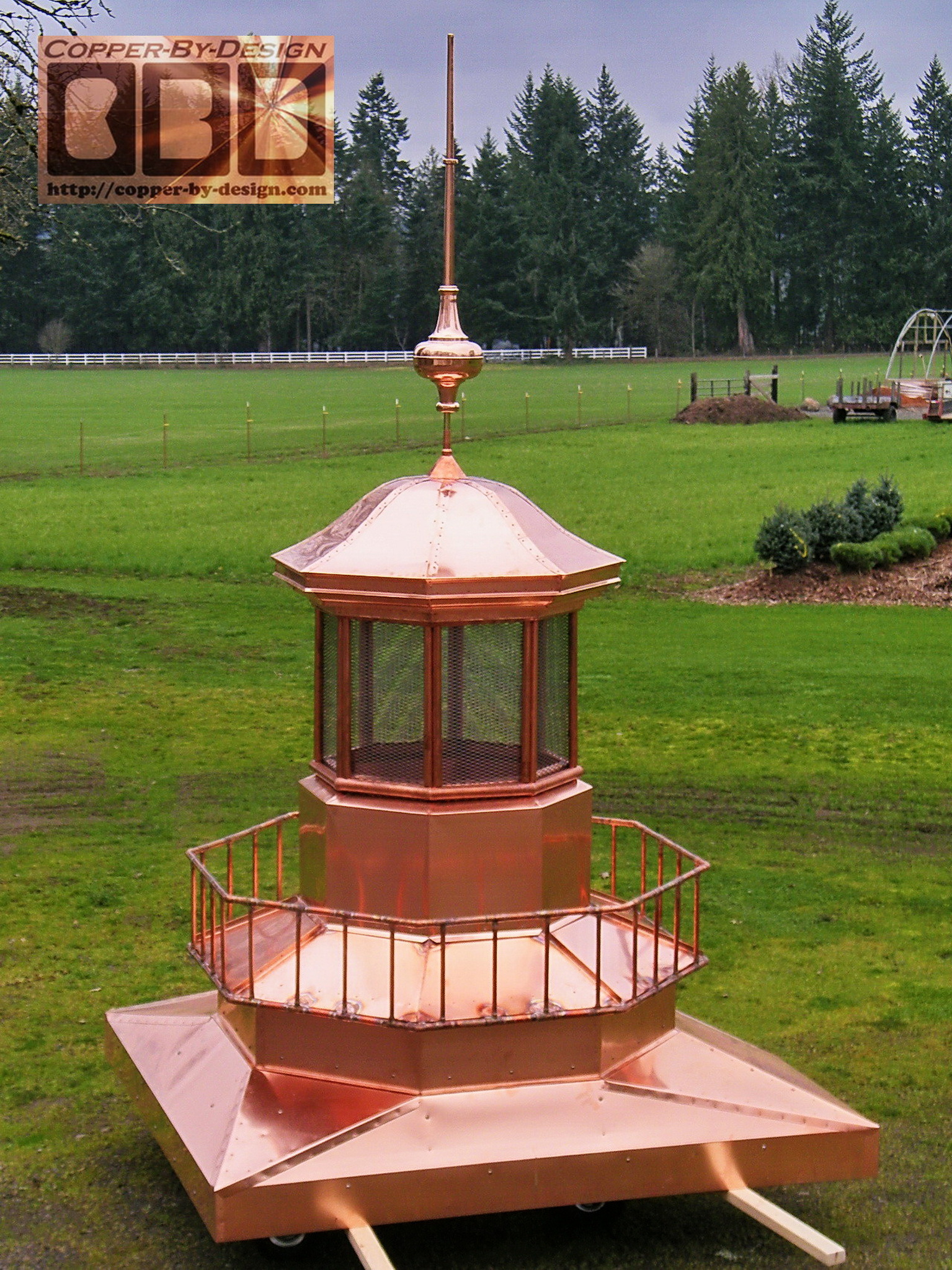
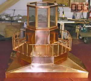
I have since changed this design even more
to enhance the look. Mainly bringing out the railing another 3"
from the base and making the upper base 6" narrower to make the
catwalk look more realistic. This is still only about 1/2 scale
of an actual lighthouse, but quite a large chimney cap at over
7' tall plus a 53" long finial above that.
|
|
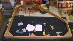 
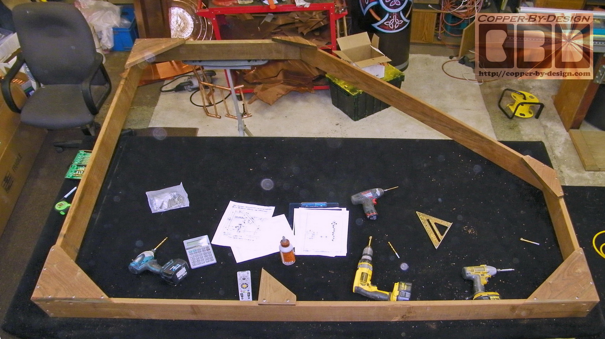
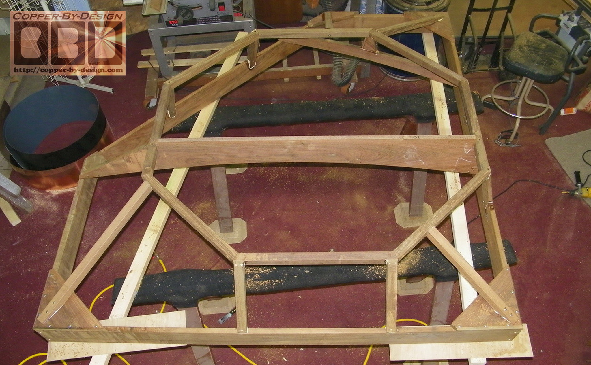
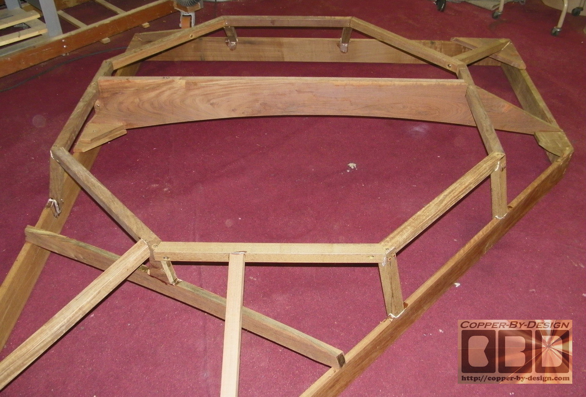
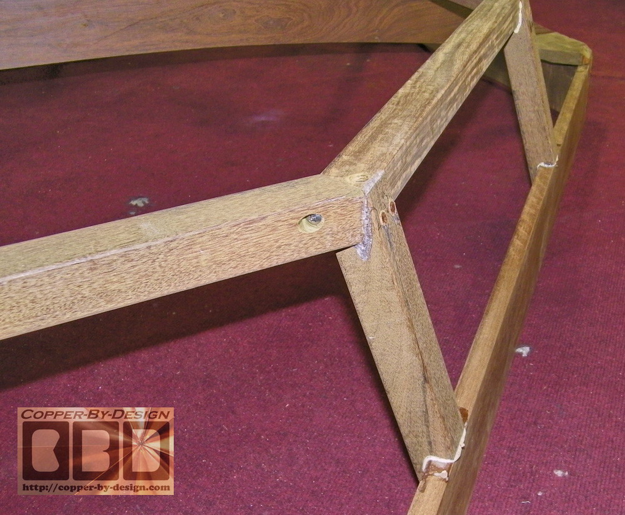
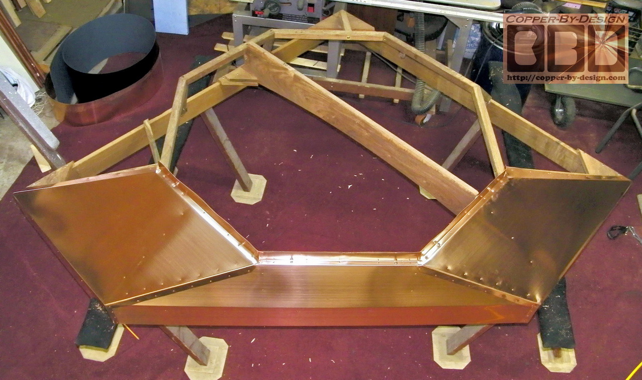
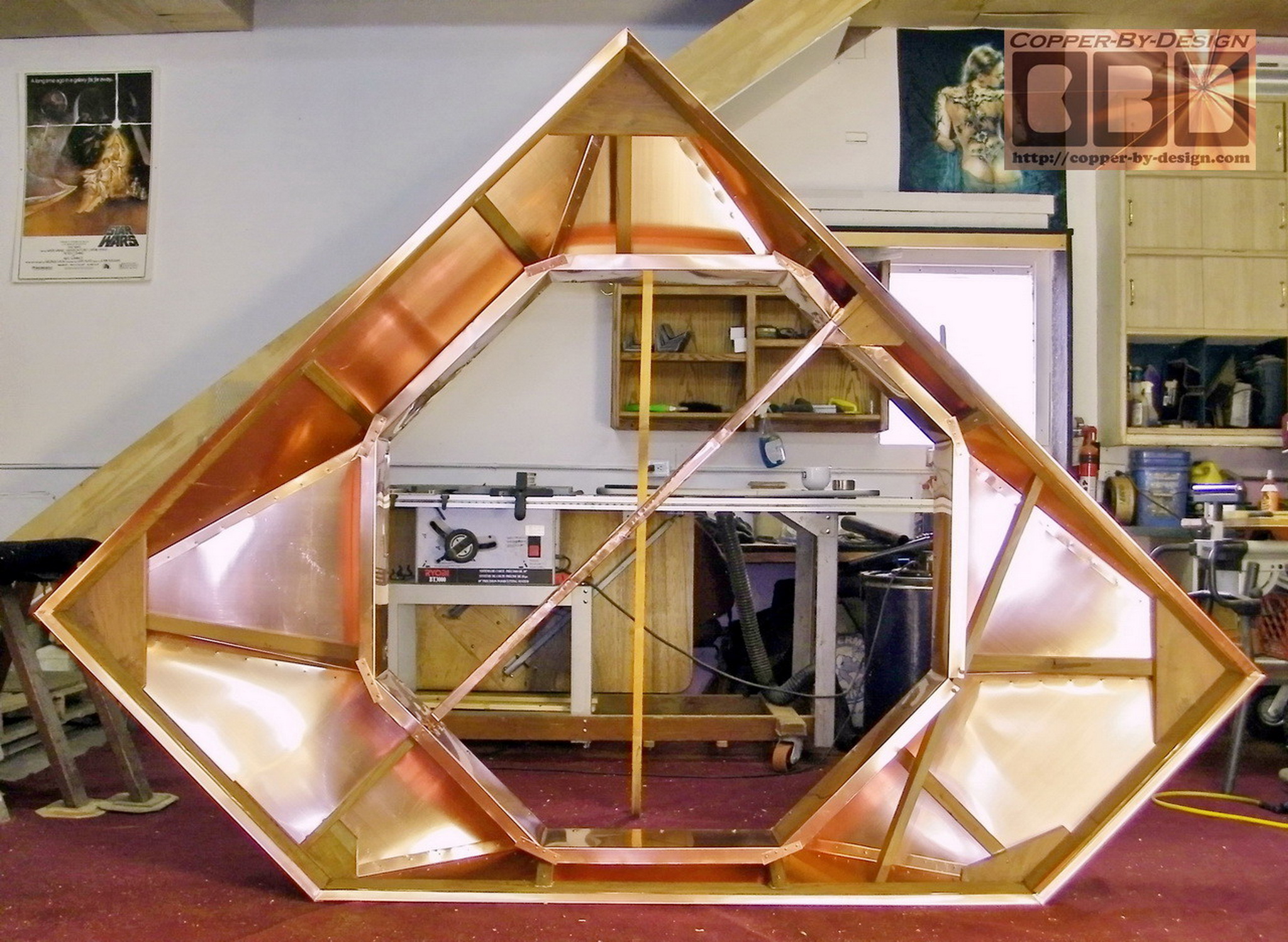
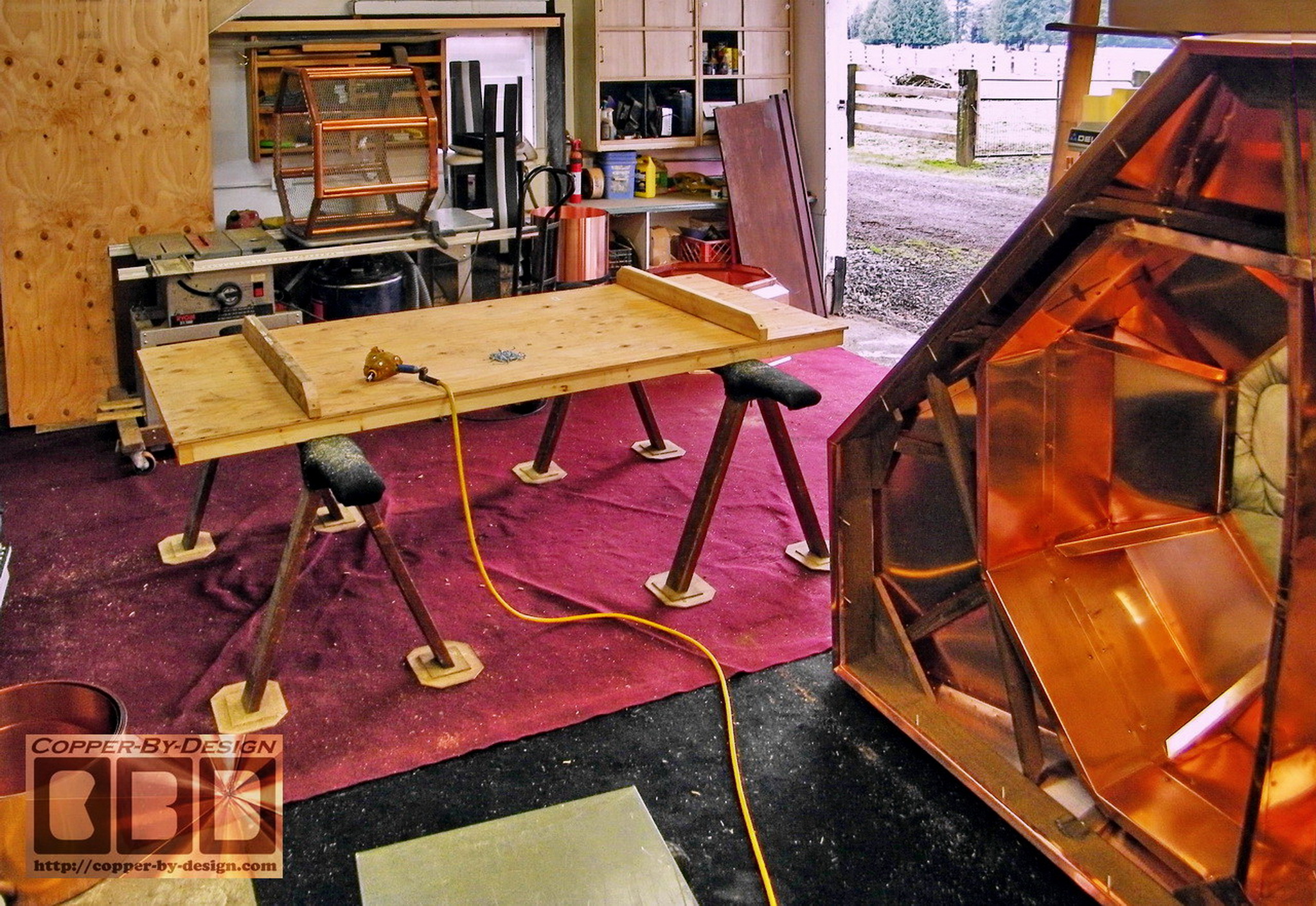
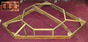
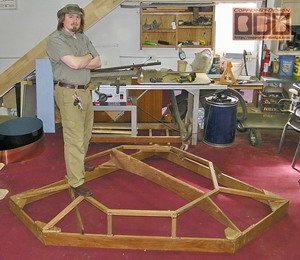
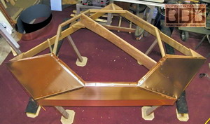
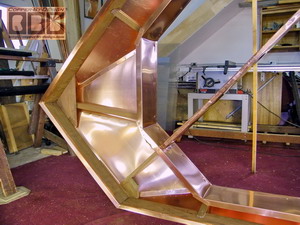
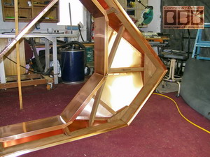
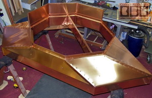
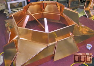
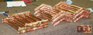
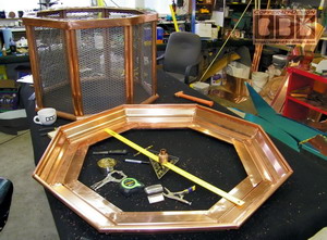
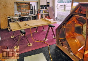
Here is some shots of the hardwood support frame I needed to build
to cover the whole top of his chimney and anchor this down in high
wind storms. This also needs to support the lighthouse shaped
chimney cap under thick snow loads of Michigan. It was important to
get the alignment just right to have this octagonal ring clear the
flue liners and have the chimney cap sit level.
This was far more tricky to
build than I had imagined. It took me a over a weeks to build and
another week to cover with copper. The weight of the chimney cap has
to be distributed out to the sides of this framework. I used
over $250 worth of this ipe hardwood; with 69.5' of boards cut
into these 32 pieces and held together with Gorilla Glue and
stainless steel screws.
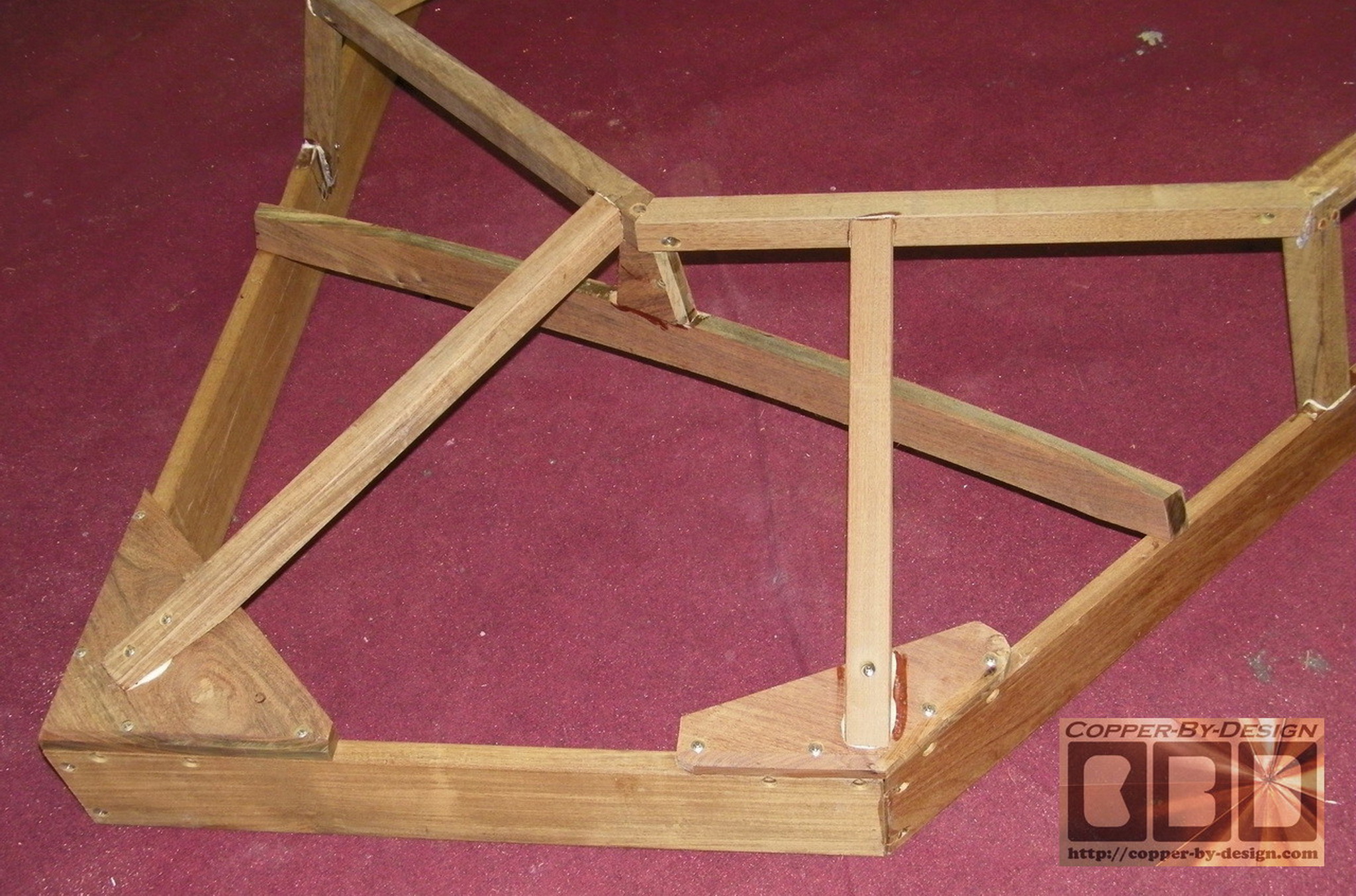
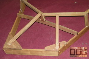
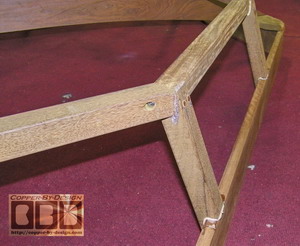
I used 9 of these 1/4" (#14) stainless steel screws to hold each
corner together, with each hole pre-drilled. This wood is so
dense and hard that if I did not drill the hole just the right
size the screw will snap off in the wood before it was cinched
down, which happened a few time building this frame.
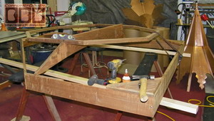
This design evolved and changed several times
before it was finished. I designed this frame with a 1/2" gap on
each side, so hopefully it will go on with out giving the
installers any grief. The corner pieces you see here are what
will rest over the top of the concrete slab.
|
|
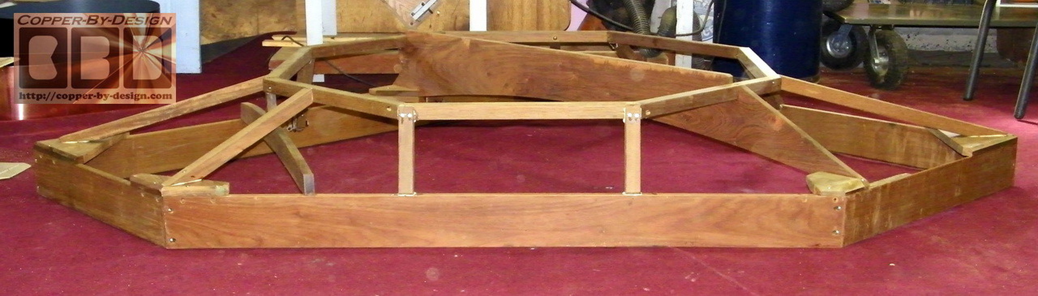
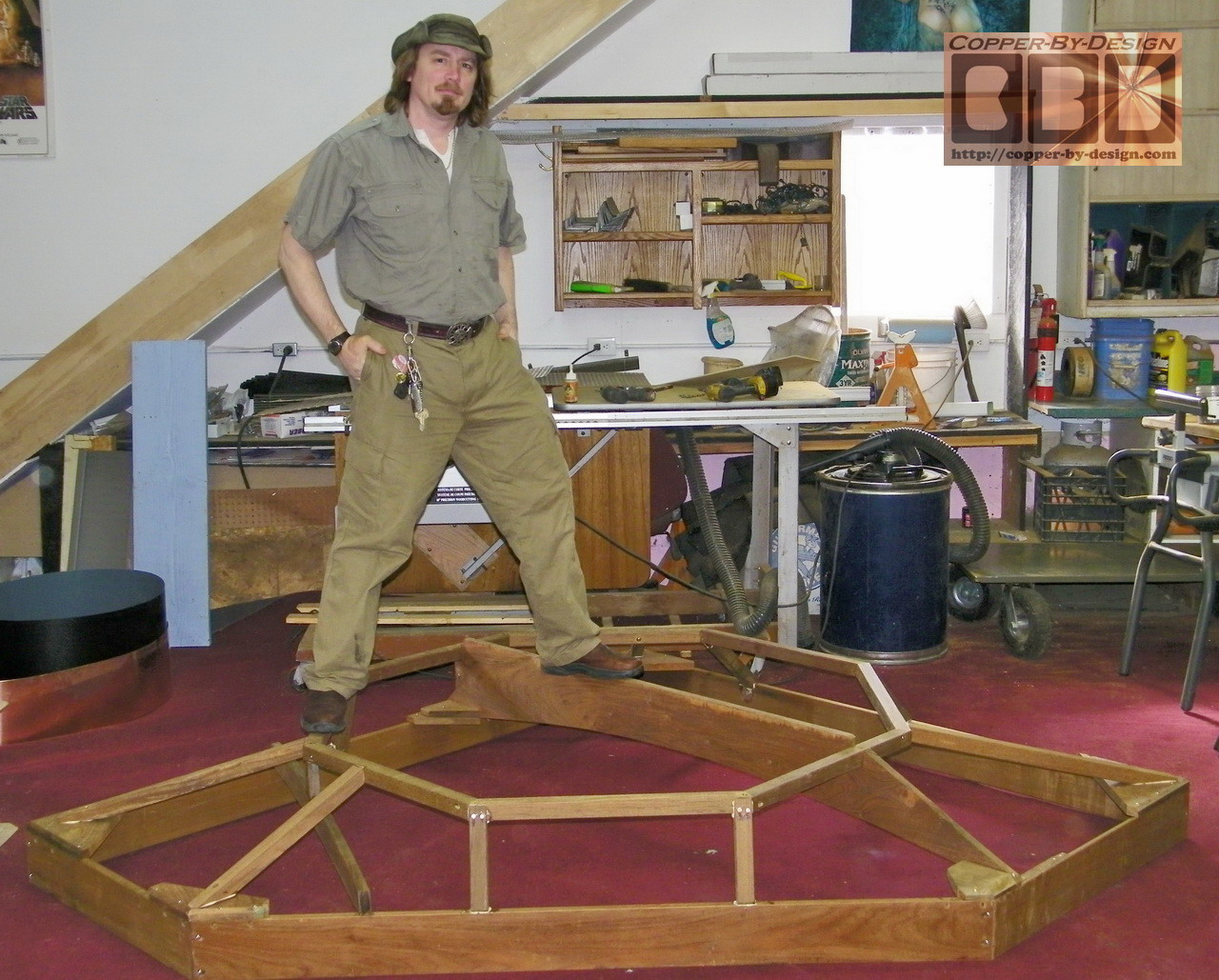
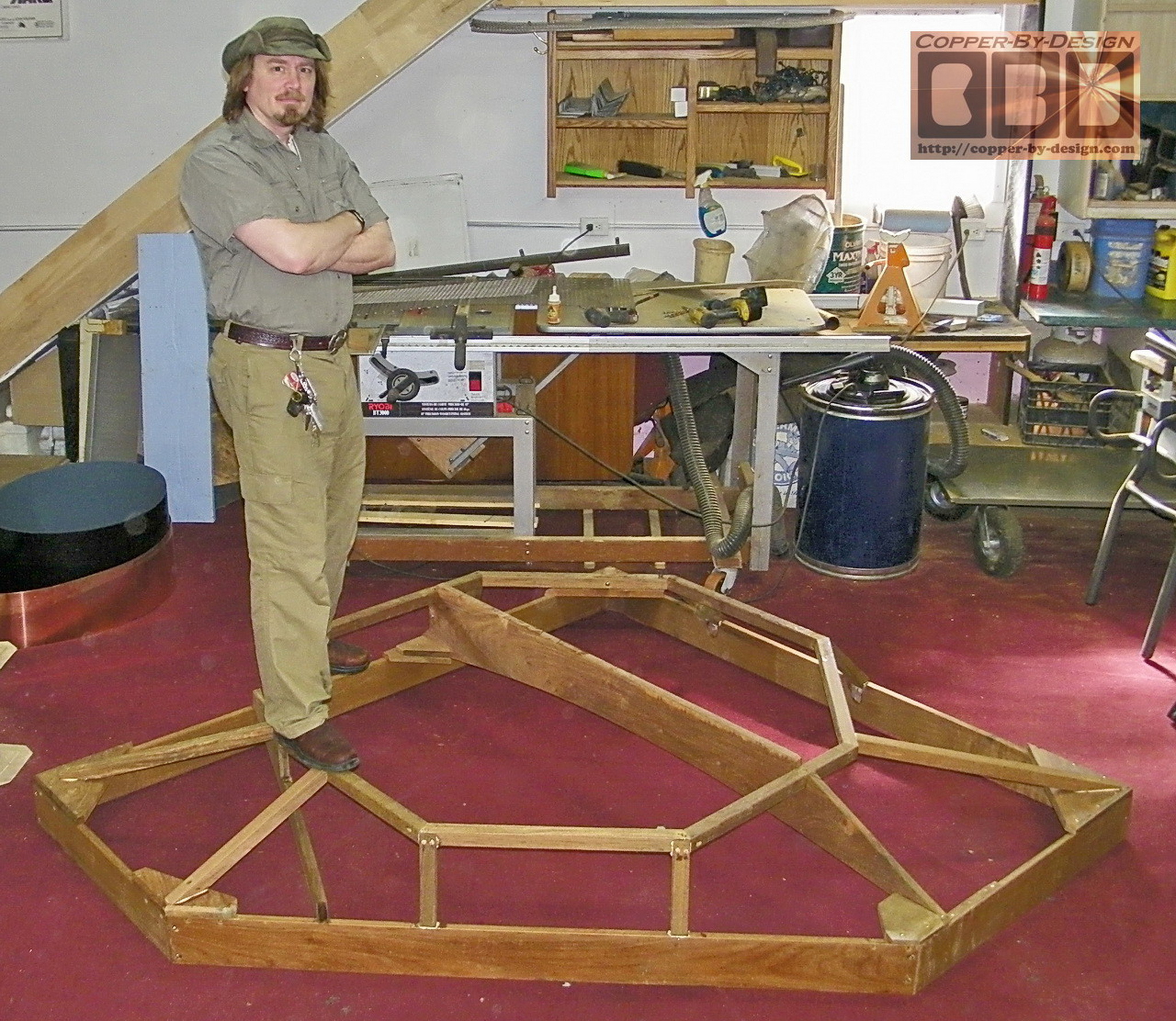
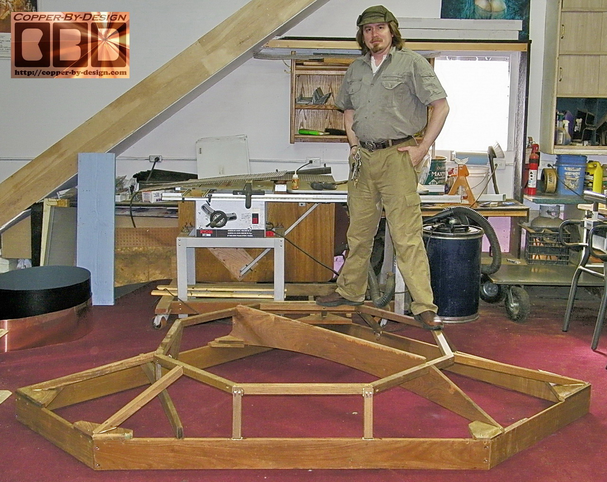
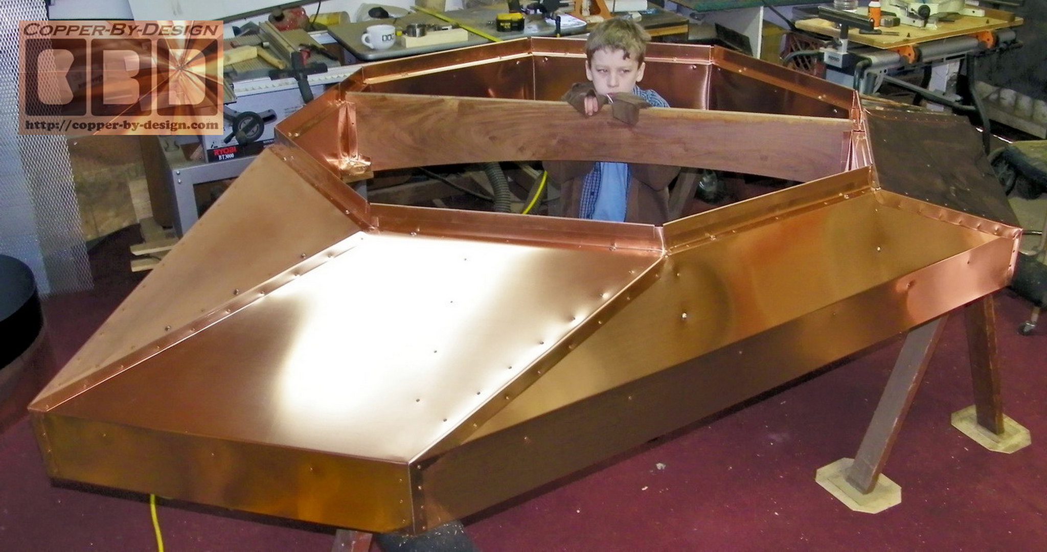
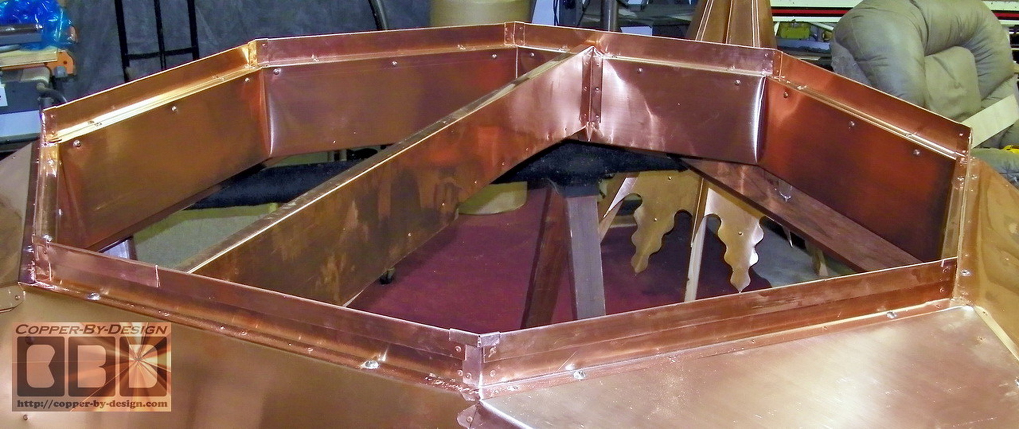
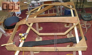
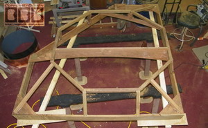
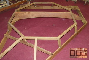
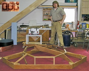
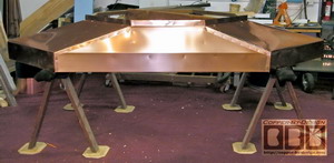
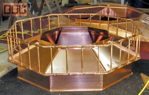
As you can see this octagonal ring is strong
enough for me stand on top of it at each side. This wood frame
weighs 115# at this point, before I covered it with copper. This
wood frame should rest just below the top edges of the flue
liners, so they should not get too hot
|
|
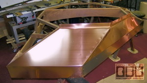
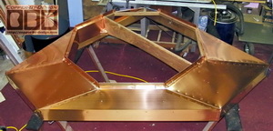
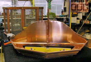
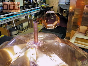
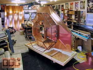
Here is some shots of this wood
framework being covered in copper with the first section started.
 I
had literally put twice as much
into his than I had predicted in the quote I sent on 7/2/08, but
I've felt this is what is needed. That still does not mean this
is going to cost you more than we had agreed on. I have also
decided to use a thicker 32oz copper for this next section that
will attach to this base/pan, in stead of just the 20oz copper I
normally use. This 11" tall section has 16.8 sq' in it, so at 2#
per sq' = 33.6#. I
had literally put twice as much
into his than I had predicted in the quote I sent on 7/2/08, but
I've felt this is what is needed. That still does not mean this
is going to cost you more than we had agreed on. I have also
decided to use a thicker 32oz copper for this next section that
will attach to this base/pan, in stead of just the 20oz copper I
normally use. This 11" tall section has 16.8 sq' in it, so at 2#
per sq' = 33.6#.
|
|
 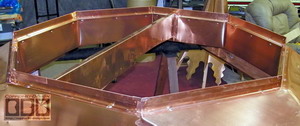
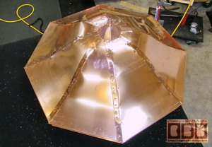
I also needed to make a liner to go inside
the ring dropping down. I also had to cover the center brace to
keep it dry and from exposure to sparks. Below are a few shots
from underneath.

|
|
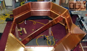
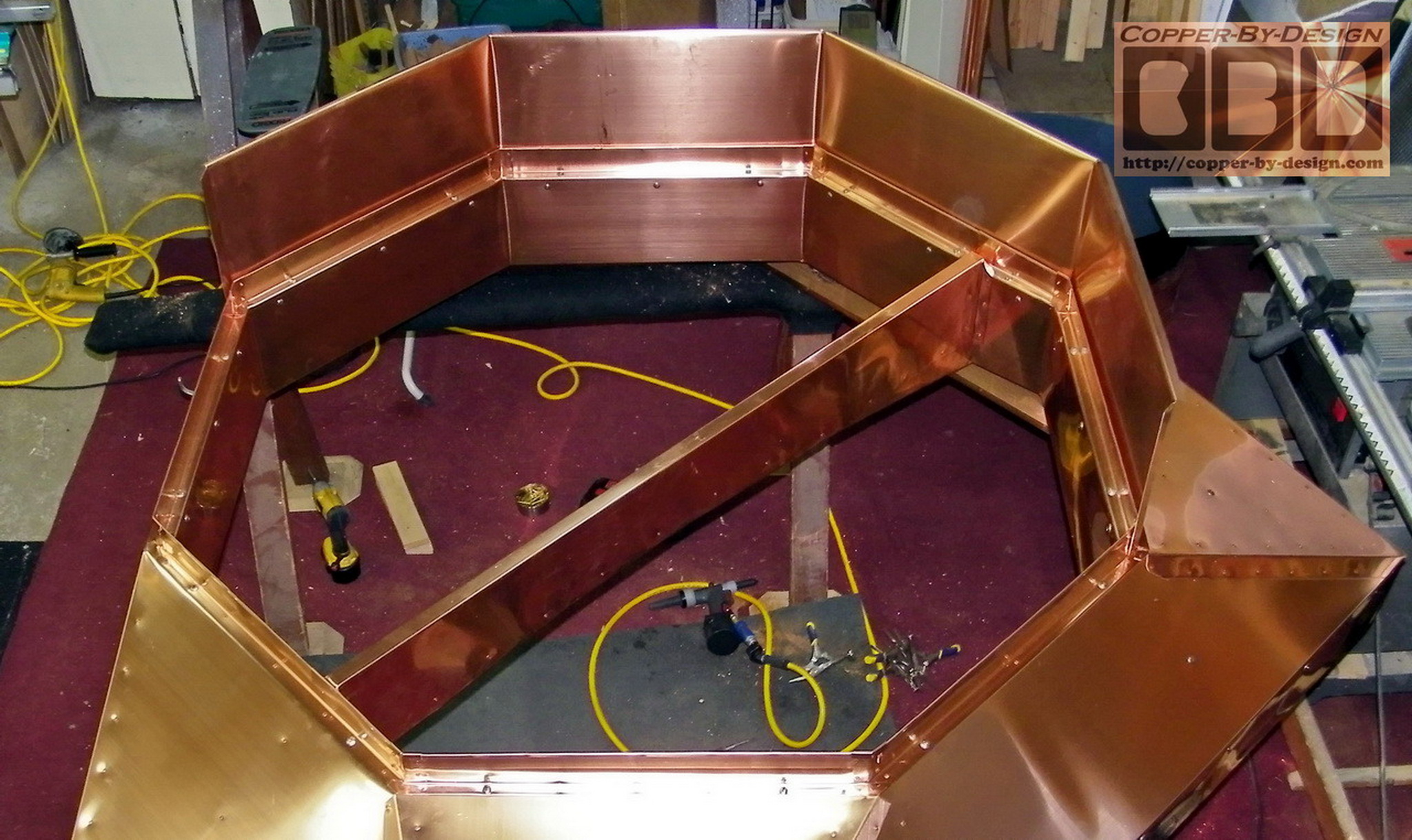
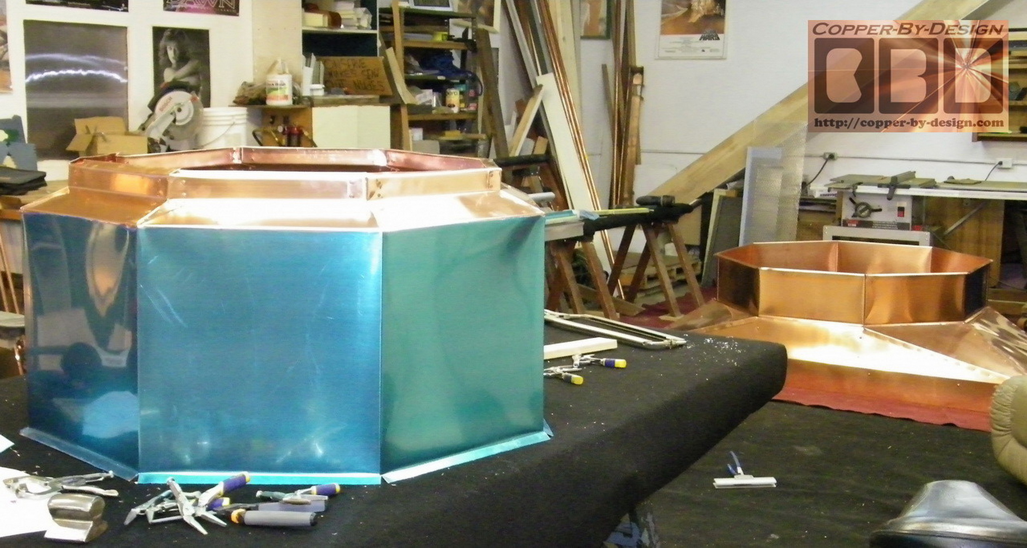
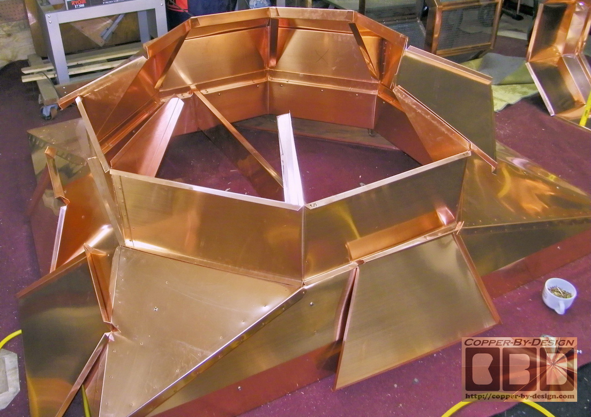
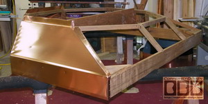
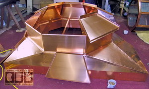
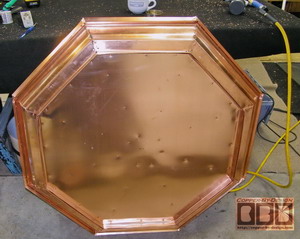
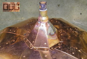
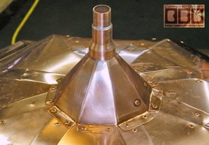
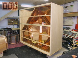
I decided to use a much thicker 32oz
copper for this next octagonal base chamber for added strength. It is
not as tall as I had planned in the diagram, since the pan is so
much taller by 9". I made it only 11" tall, in stead of 16"
shown in the diagram.
|
|
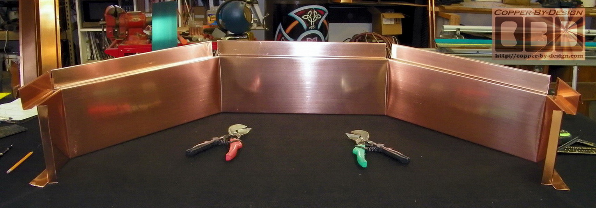
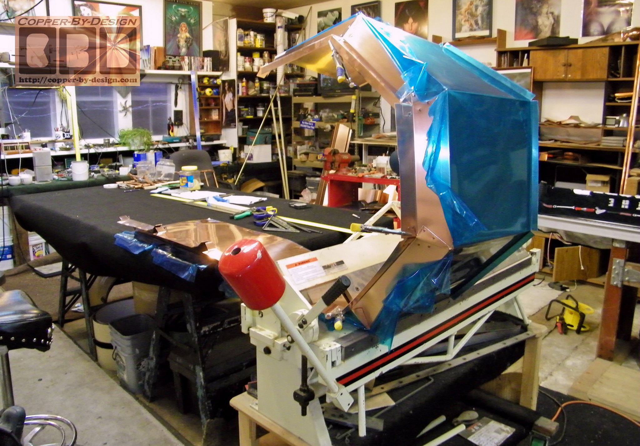
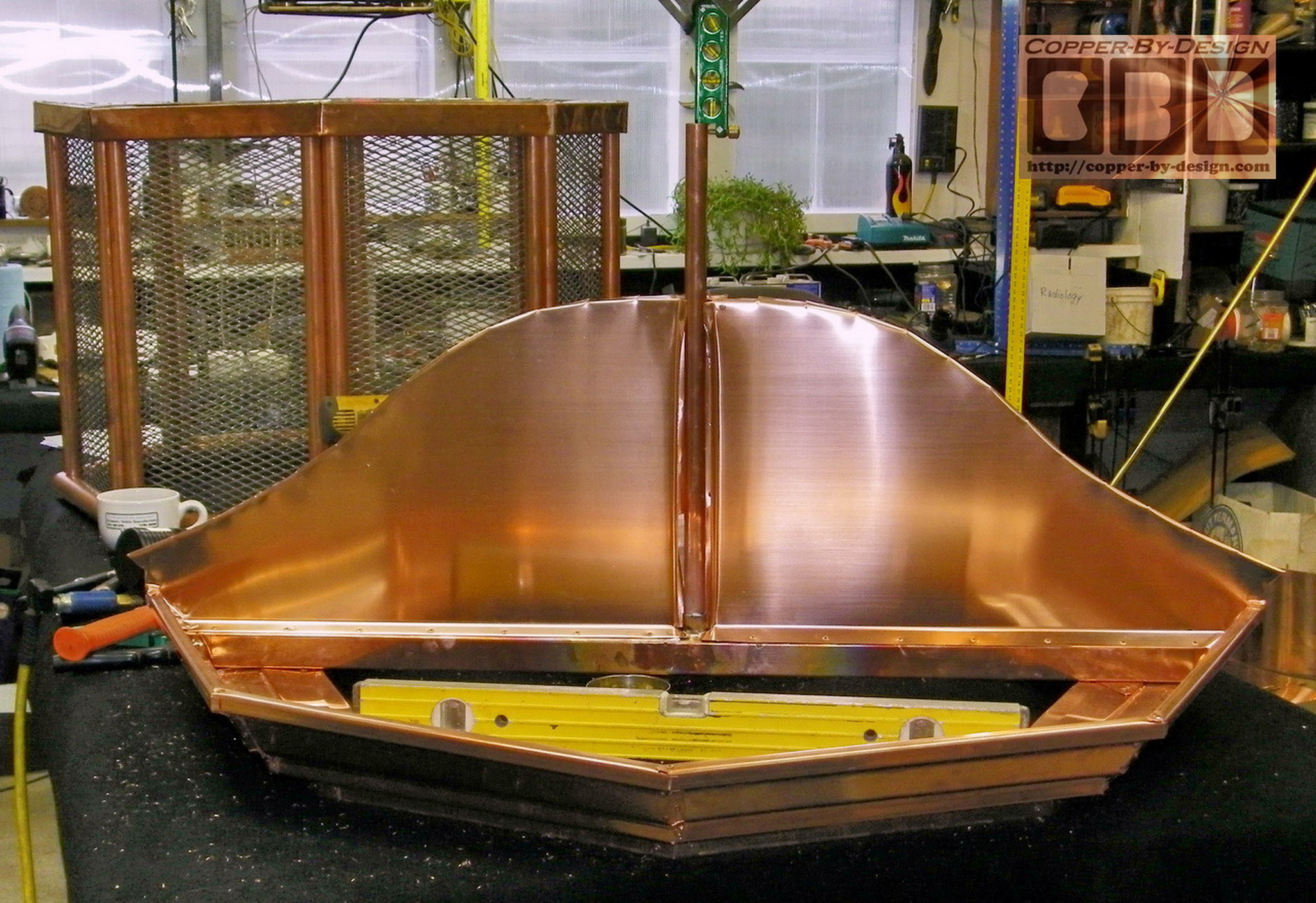
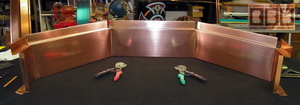
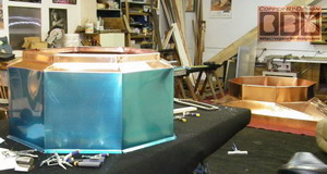
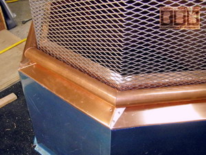
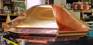
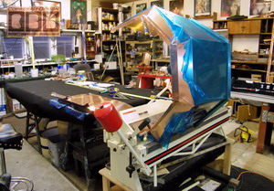 These pics show the mid section being formed that goes
just under the vent windows. The blue is just a plastic film
over the copper. I decided to make this chamber a
little smaller at just 3' wide, so there is a more noticeable
transition from the lower section. The railing will be 3" set
out past the 4' 9" wide base bringing the difference from 9" to
14", so it will look more like a full catwalk. These pics show the mid section being formed that goes
just under the vent windows. The blue is just a plastic film
over the copper. I decided to make this chamber a
little smaller at just 3' wide, so there is a more noticeable
transition from the lower section. The railing will be 3" set
out past the 4' 9" wide base bringing the difference from 9" to
14", so it will look more like a full catwalk.
|
|
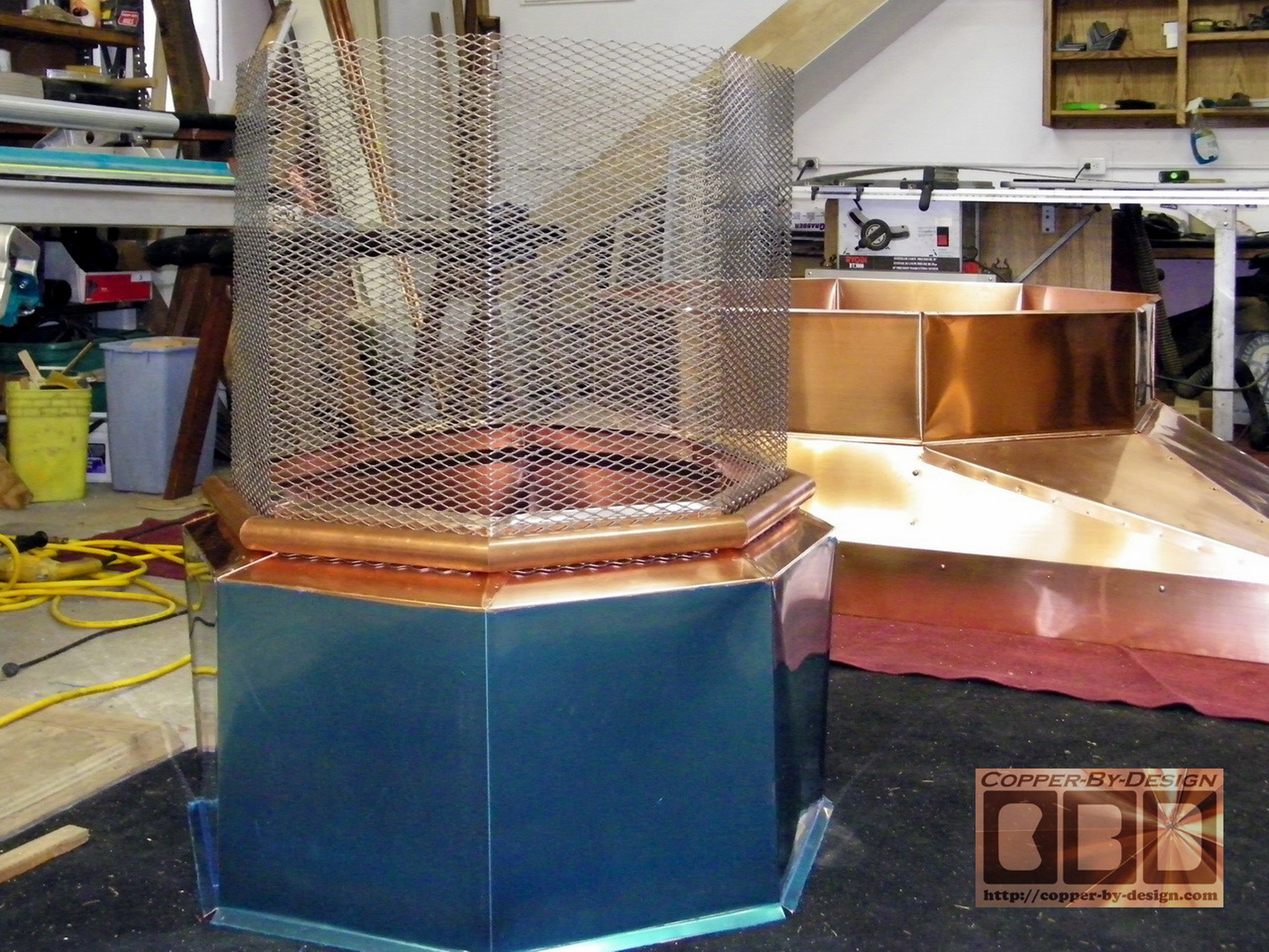
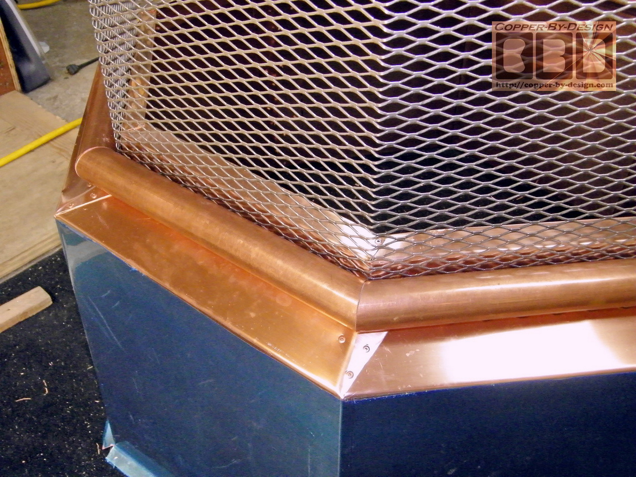
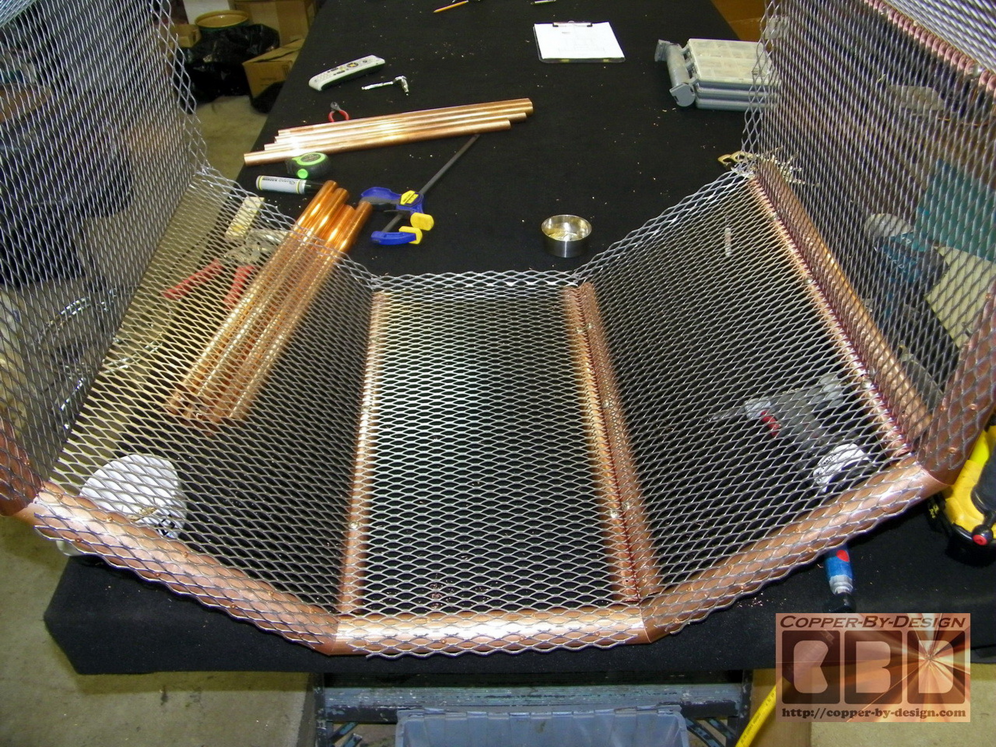
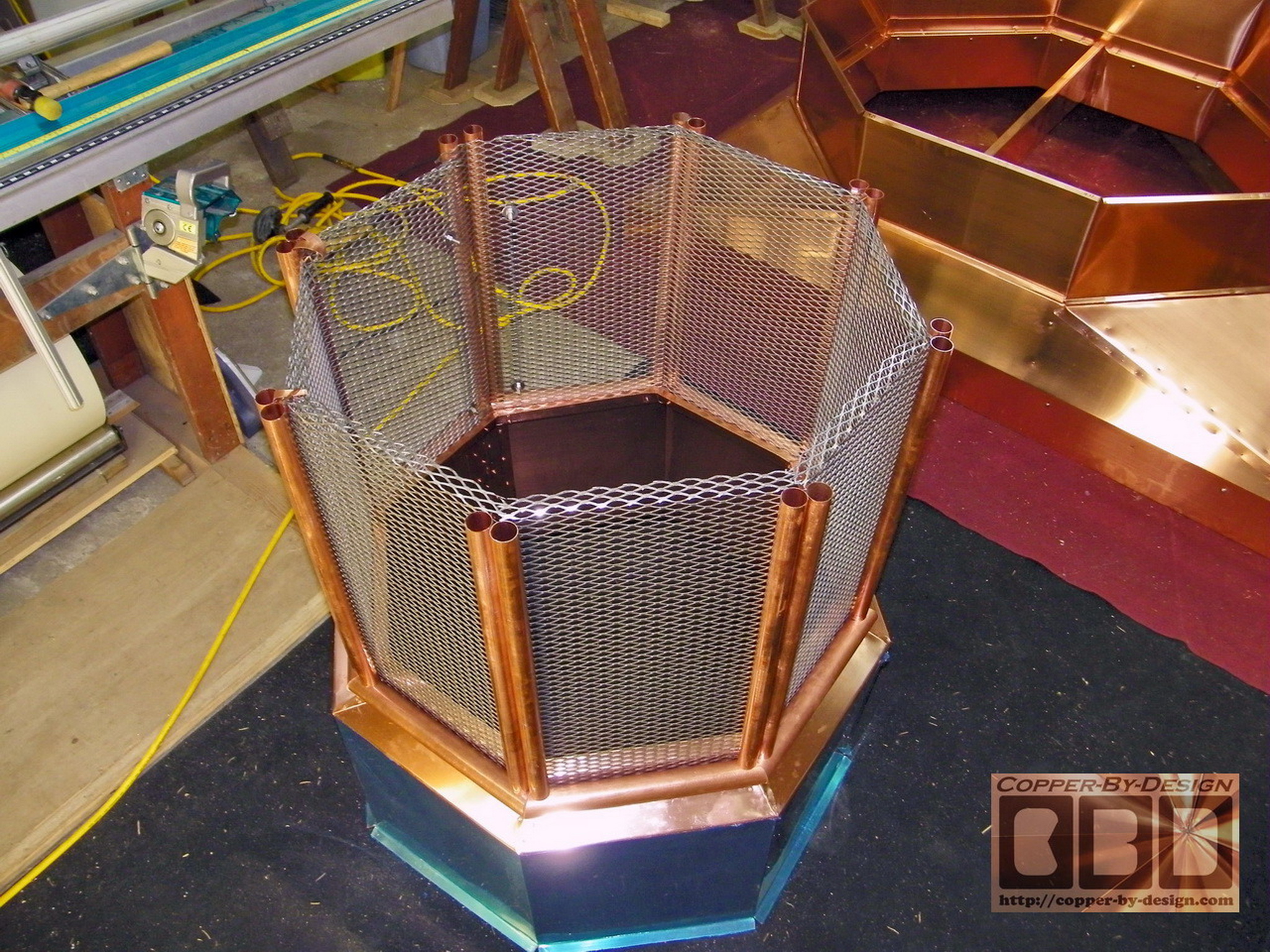
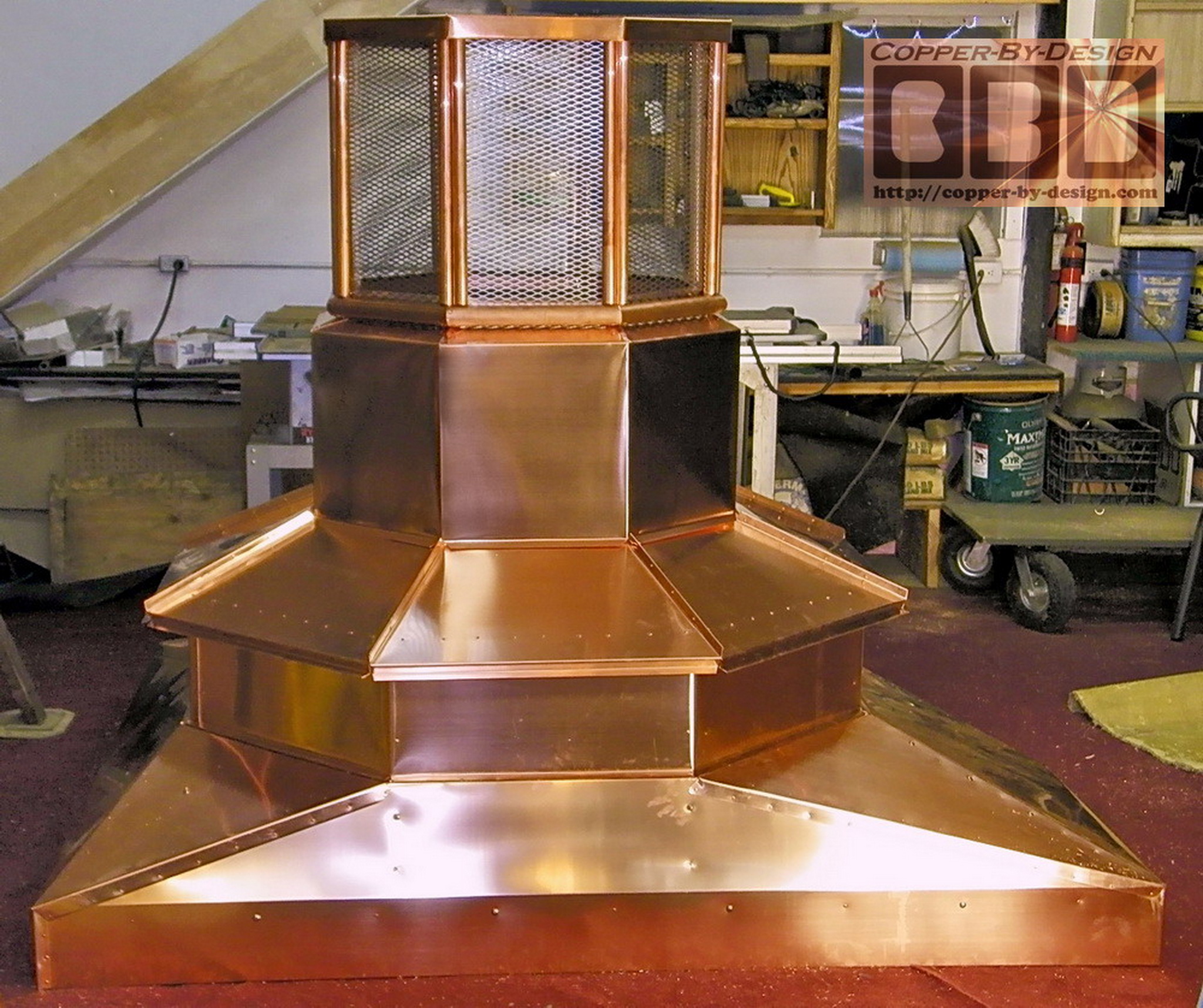
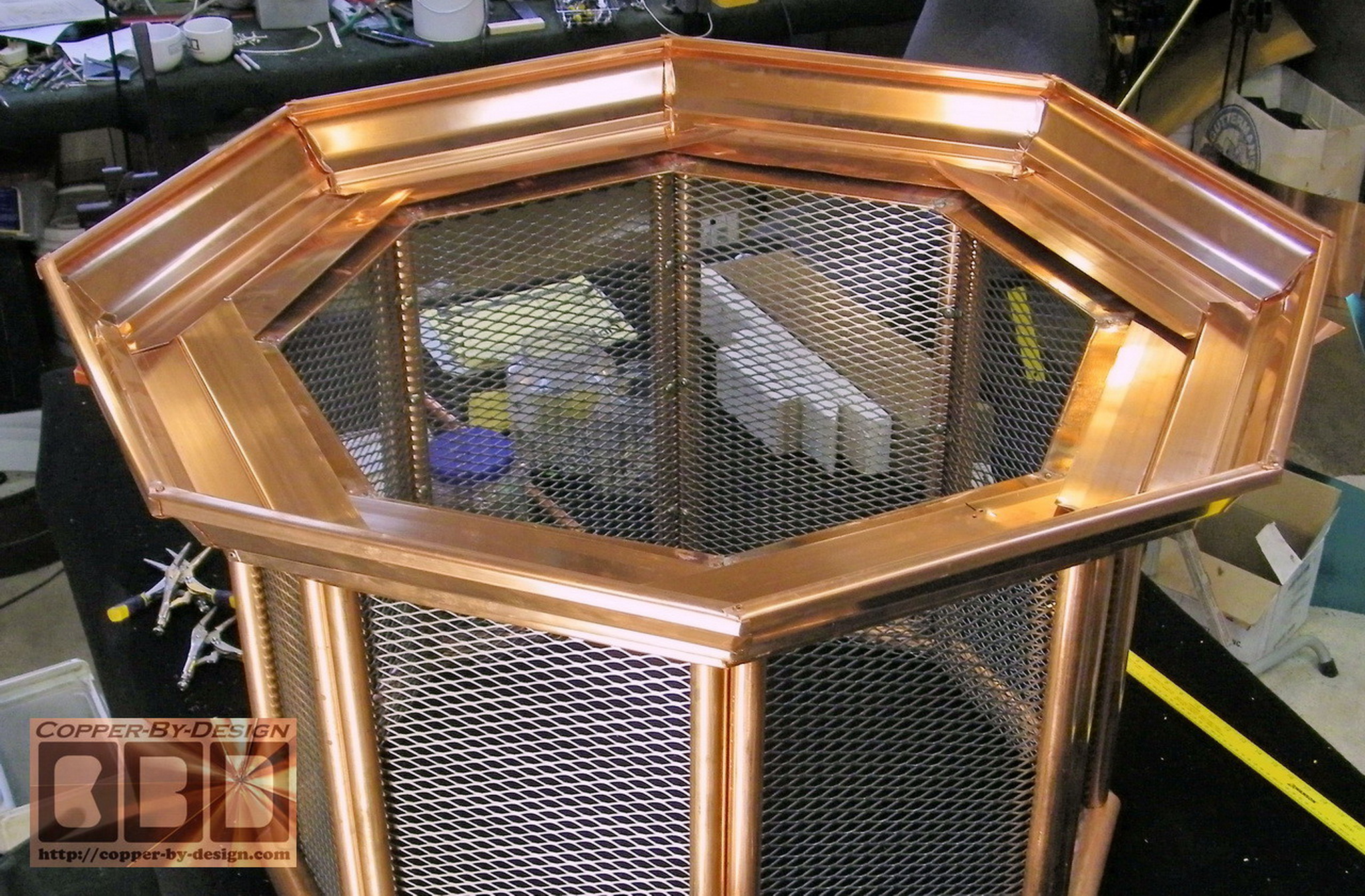
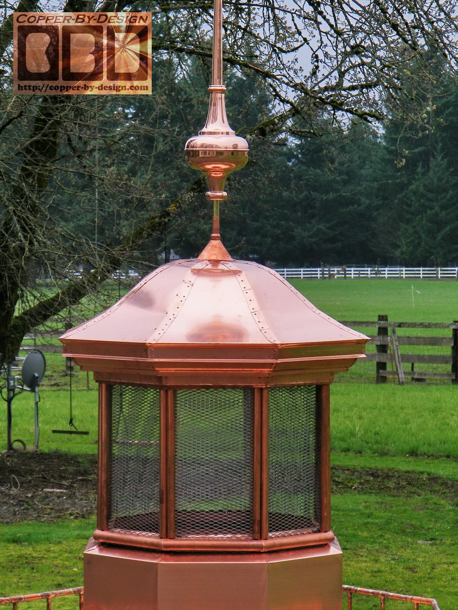
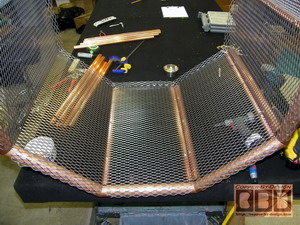
This is the SS screen vent section that is
to resemble the windows/light part of a lighthouse. In stead of
bending copper sheet metal to frame this I decided to use copper
pipes. At the base is less than 10' of 1.5" copper pipe,
which happen to cost over twice as much as the 32' of 1"
vertical pipes I used here. They do
sell 45 degree pipe connectors, but I wanted a more sharp look
at the corners, so I cut them at a 22.5 degree angle on each end
for these to miter together at this 45 degree corner. It is then
riveted to the screen from behind and underneath with a copper
plate under each corner.
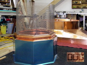 
I used a pair of 1" copper pipes for the
corner framework attached from inside, so that took 32' of pipe
to make just this little 2' tall section, yet still did not cost
even 1/3 what that 10' base pipe cost me.
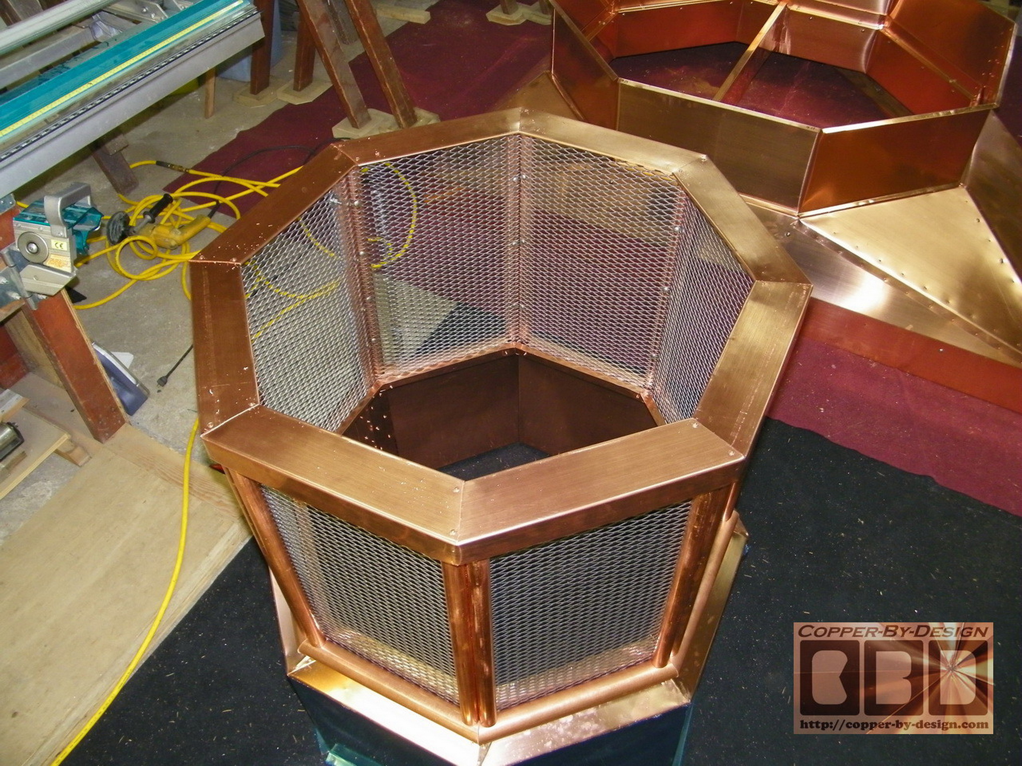
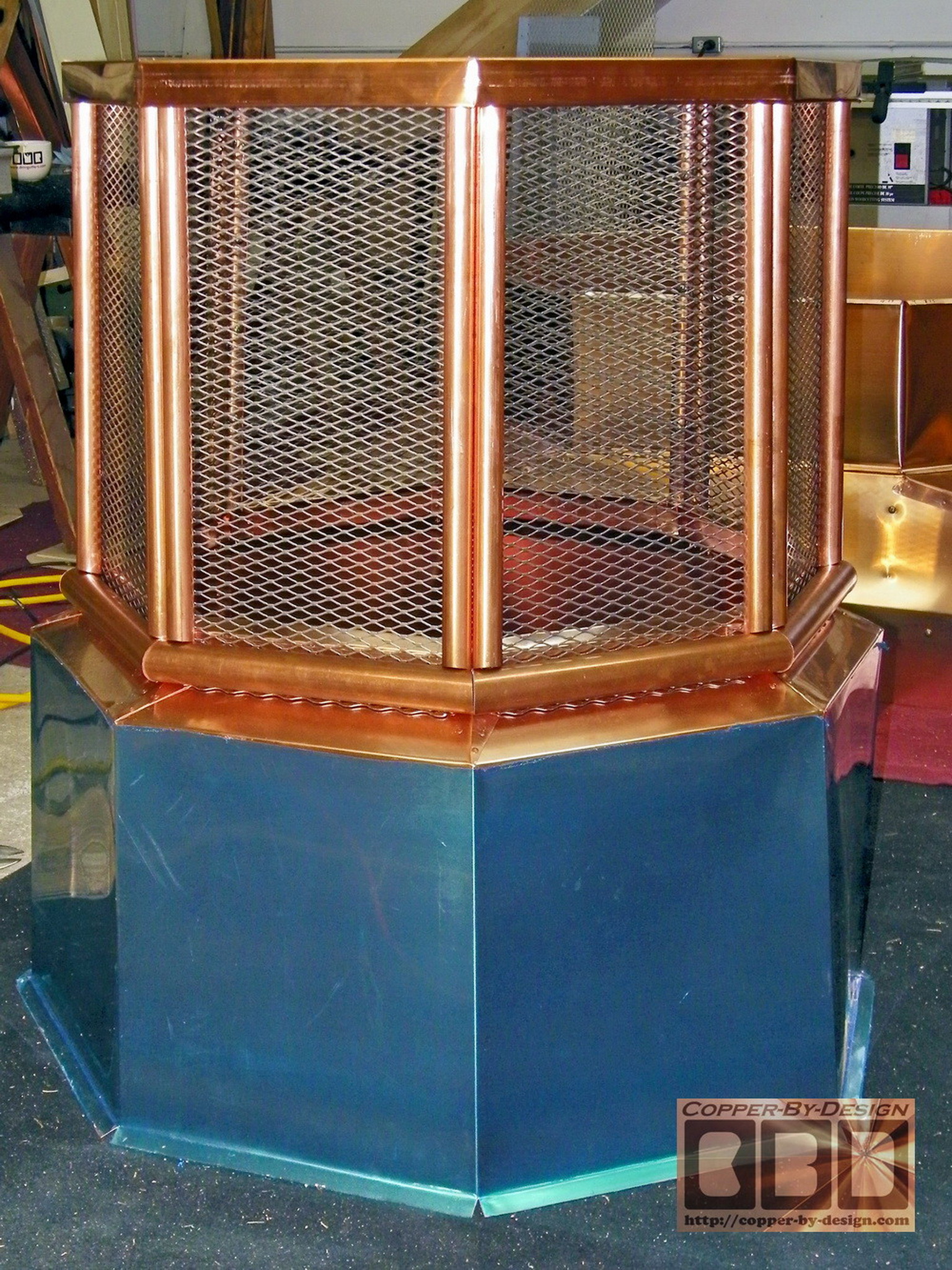
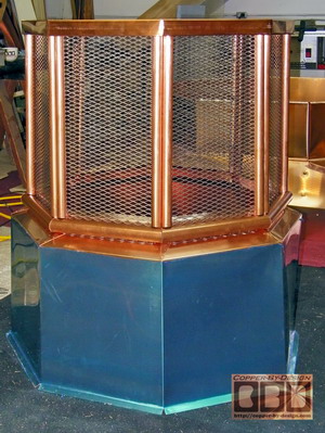
Here is it with the cap metal formed and
attached to this section, which is now 24" tall and 33.5" wide,
not including the copper chamber it is sitting on.
|
|
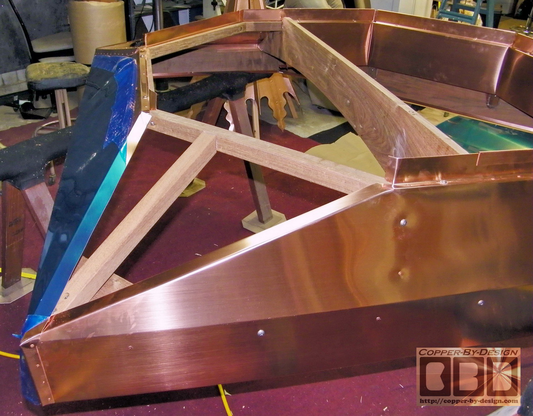
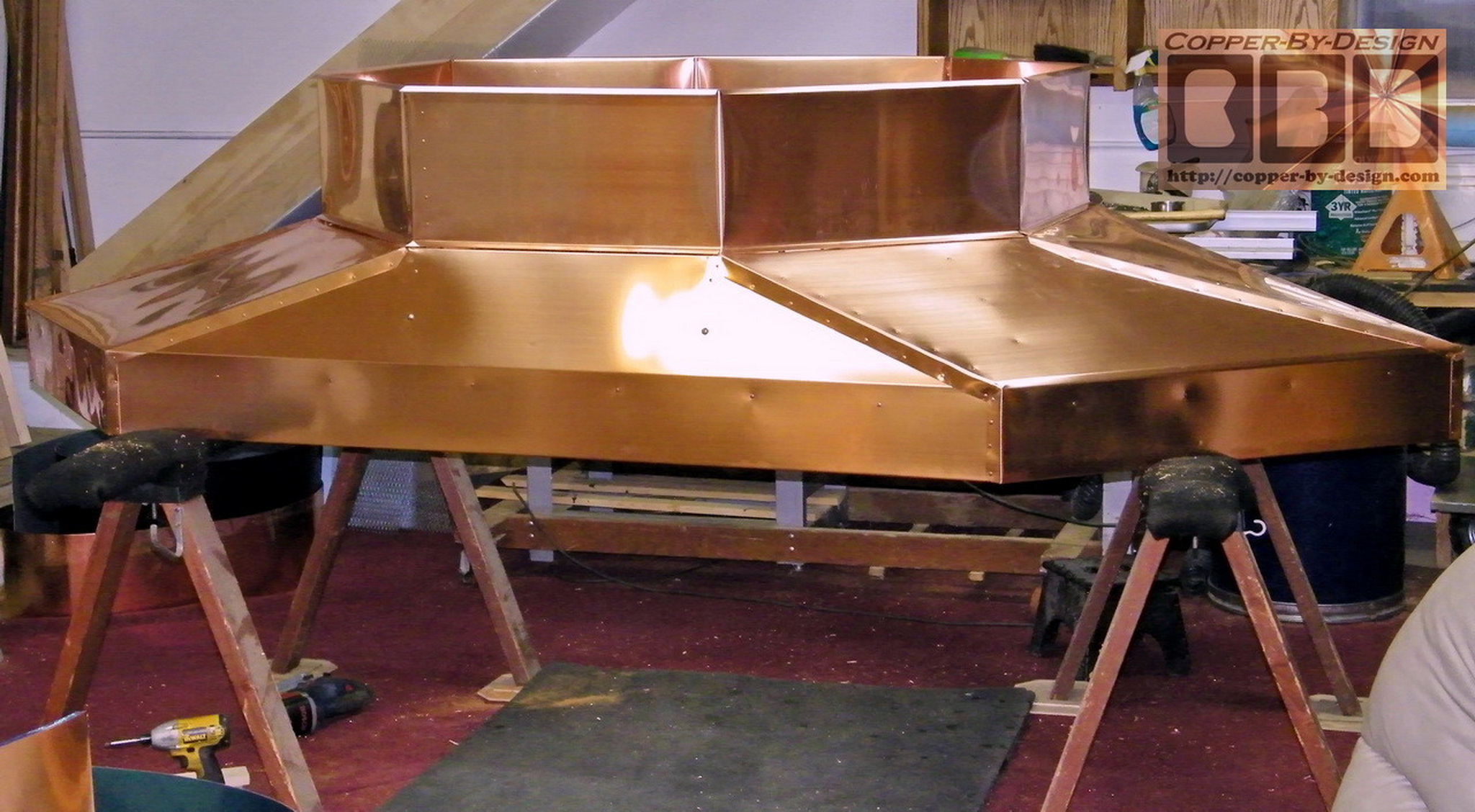
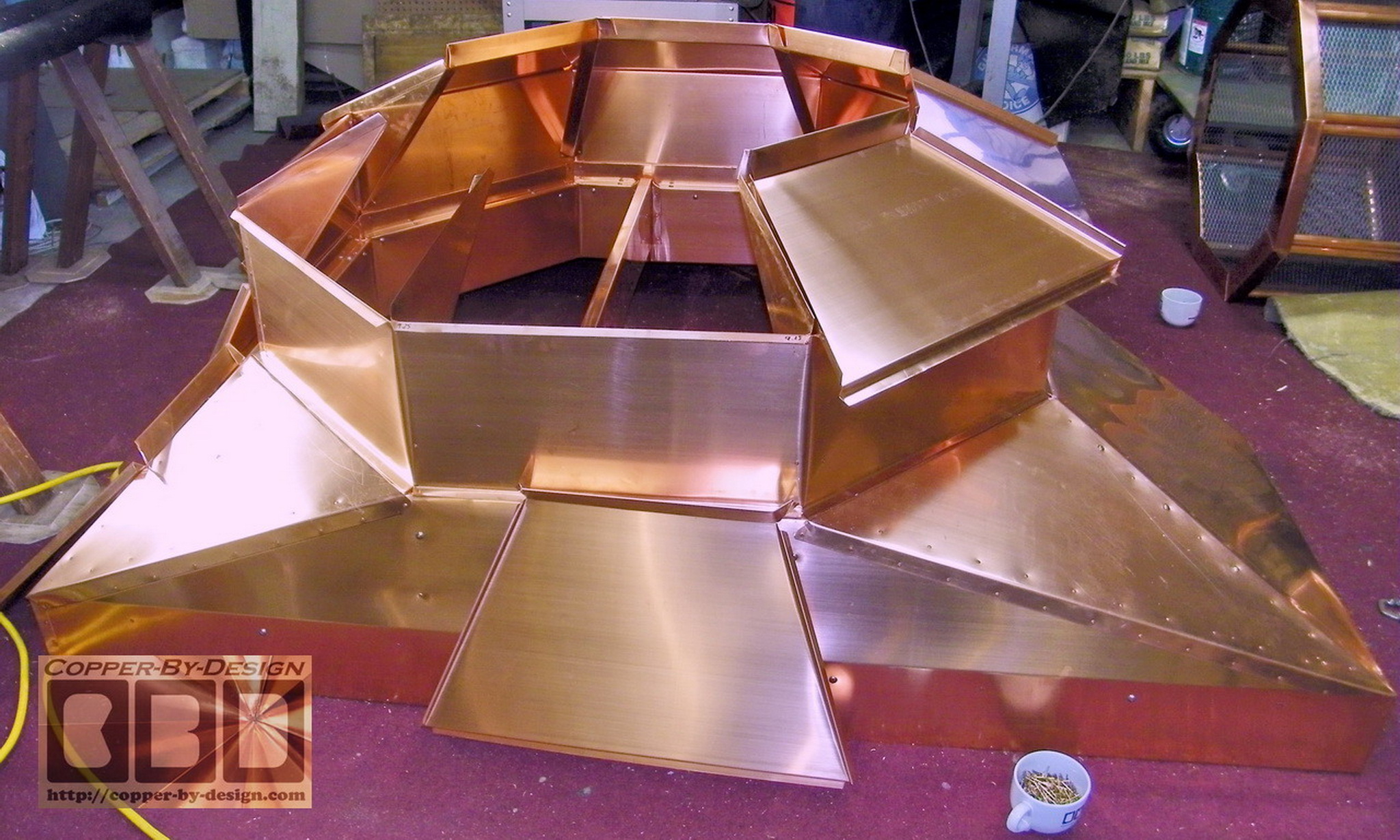
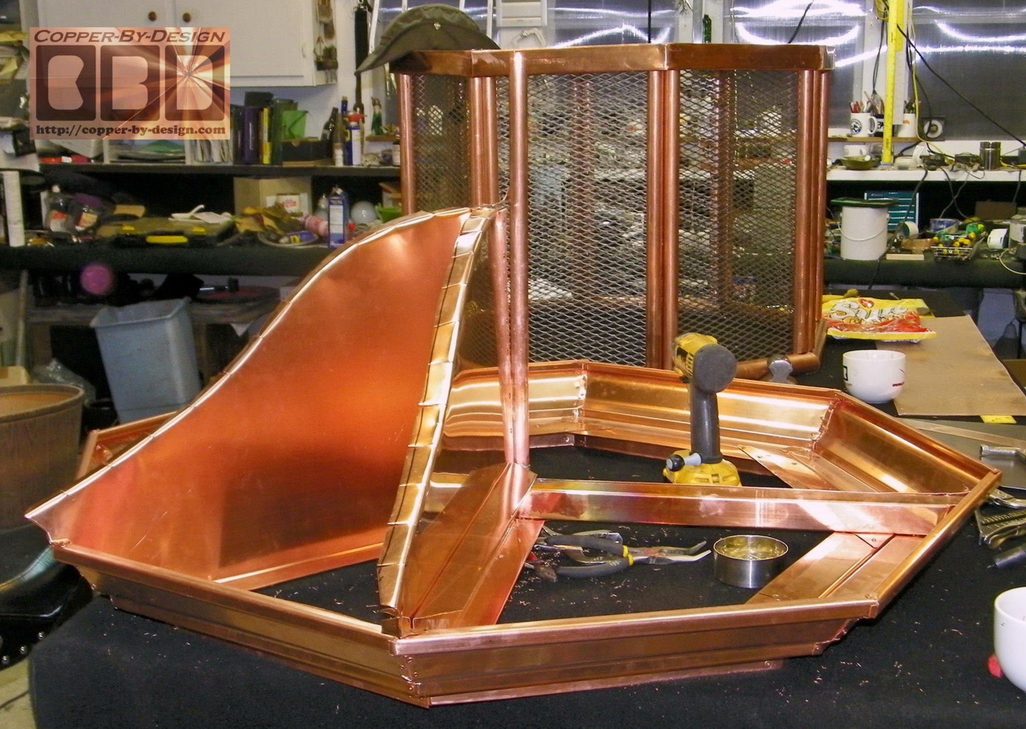
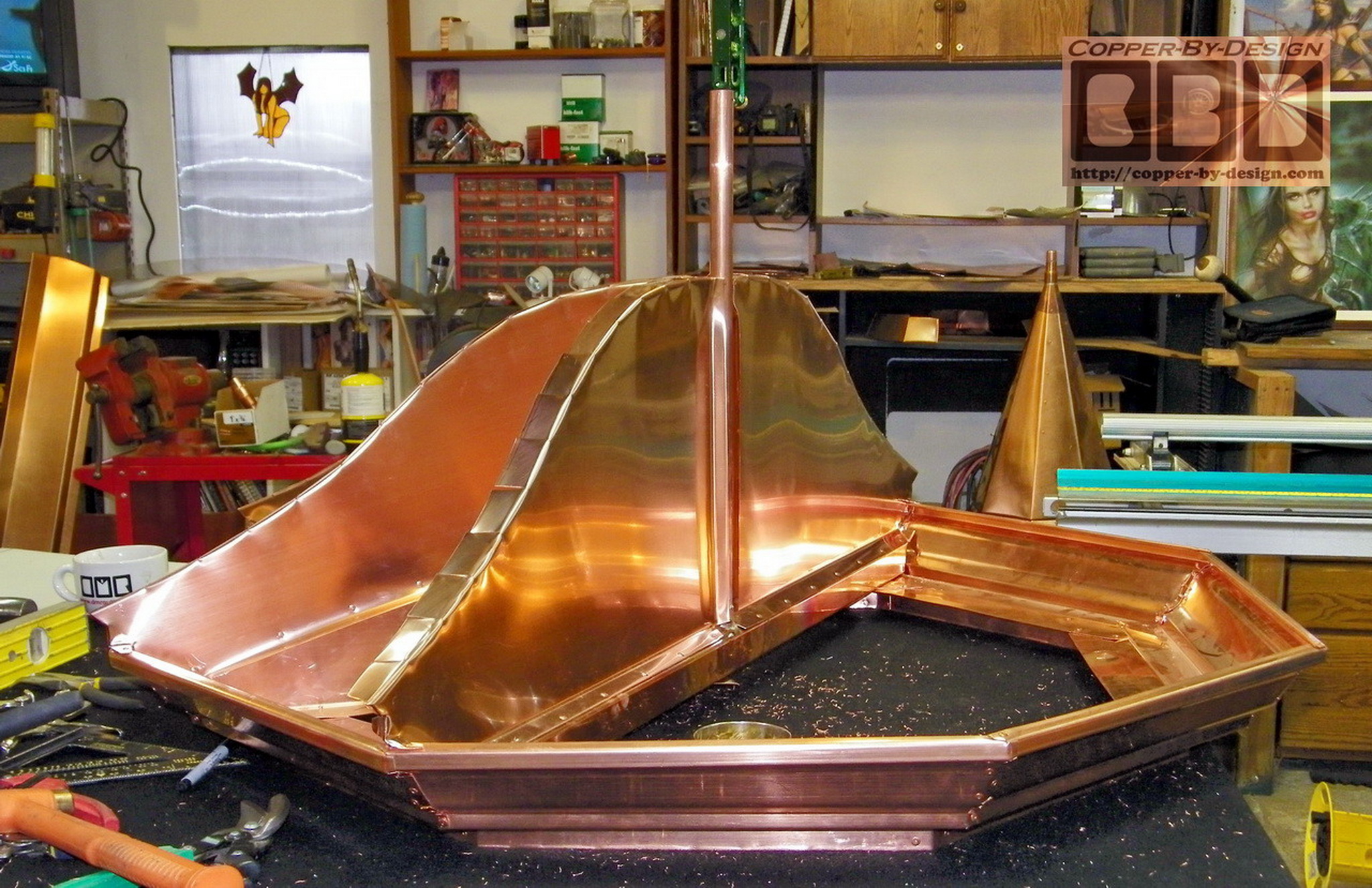
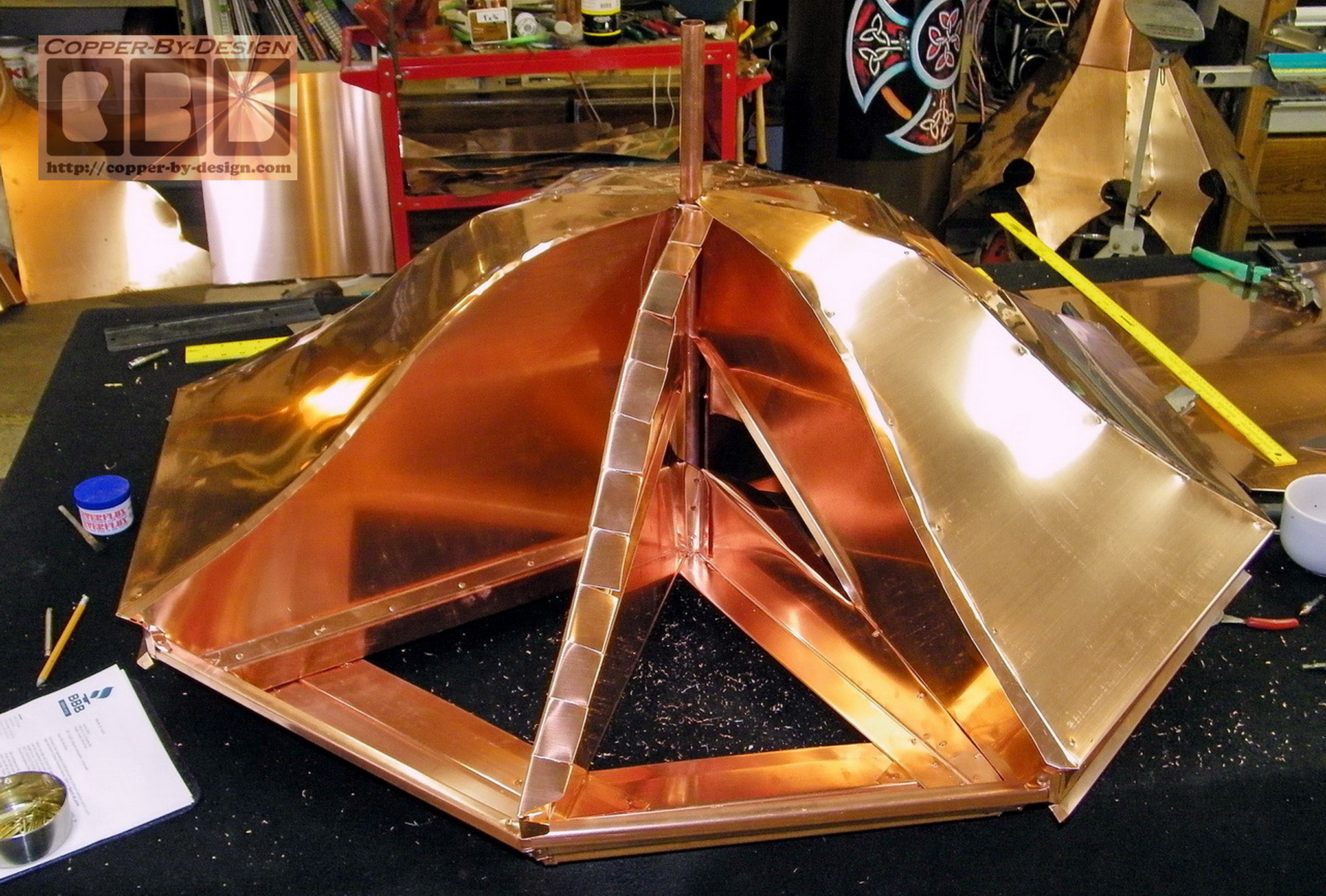
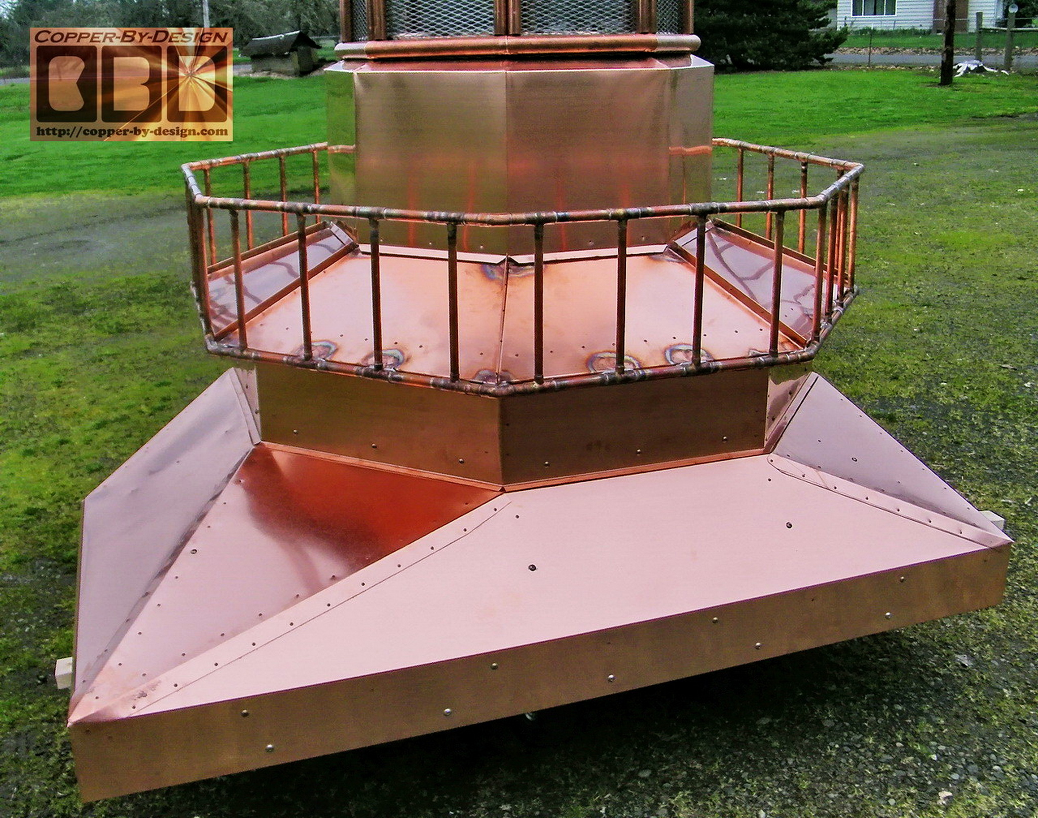
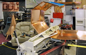
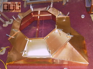
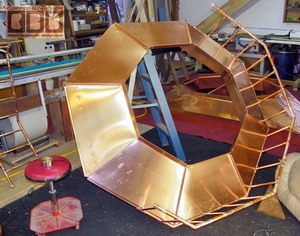
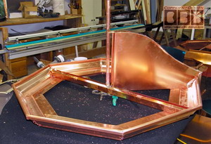
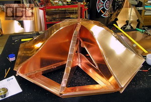
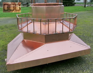
Here is the copper sheets for the graduation
from the first octagonal base chamber up to the upper base
chamber. I angle it with a 6/12 pitch the be sure to shed not
just rain water, but fallen debris from tree as well. This angle
also adds a lot of support strength. I would normally not build
this with standing seams, but it was the best way to connect the
triangular support pieces underneath.
I made these internal
supports to help hold the weigh of the sections above with snow
loads. I also chose to extend this tapered cover a 3" inches
out past the sides of this section to attach the railing to, so
it looks more like the light house in the photos he sent than the diagram shows.
|
|
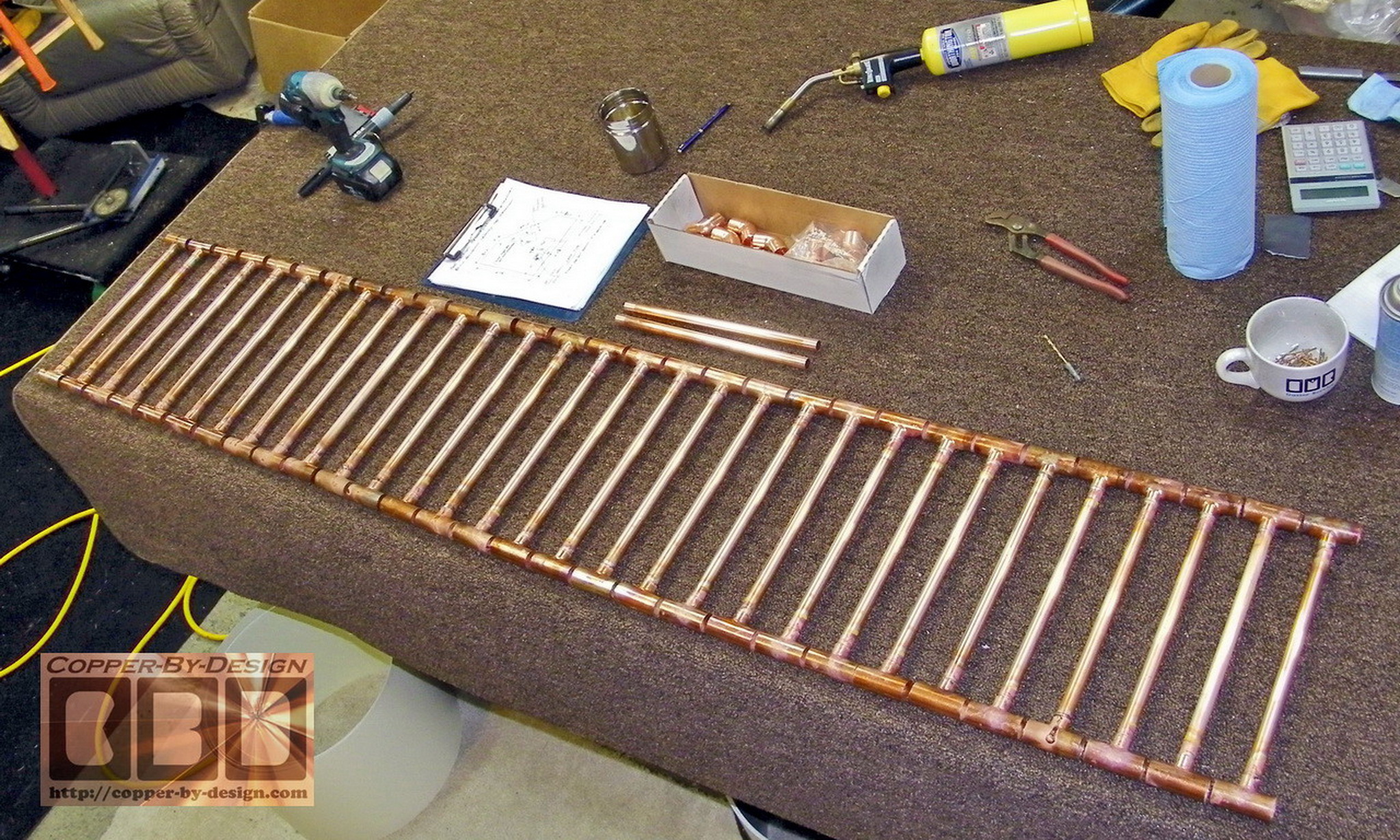
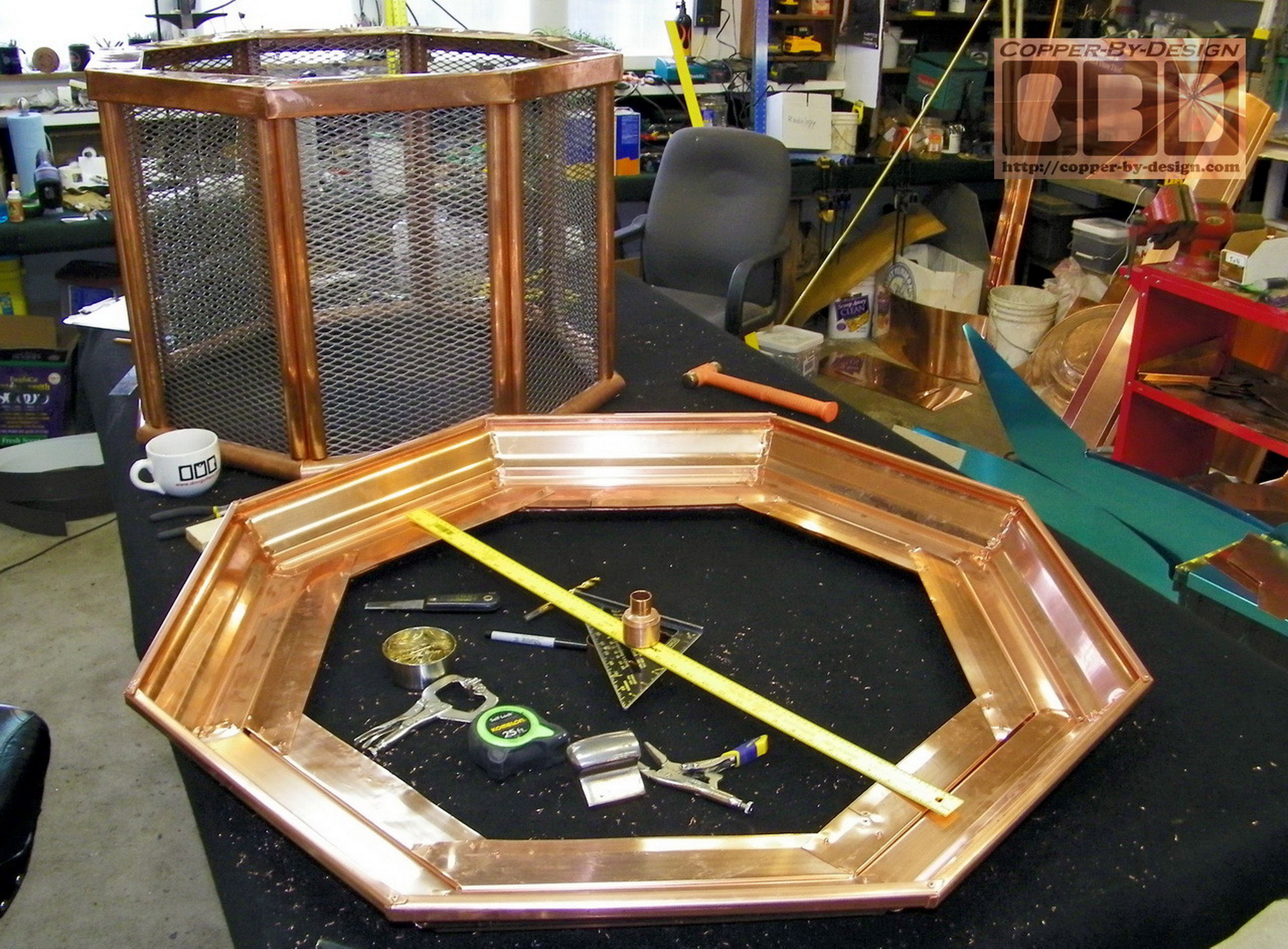
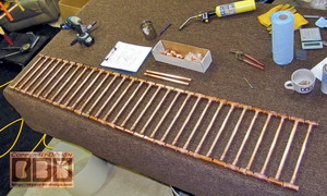
Here is the copper pipes for the railing. I
used 29.75' of 3/4" pipe for the top and bottom horizontal rail, and
32' of 1/2"
pipe for the vertical railing. This required 80 connectors to
solder to these 112 pieces of pipe together to form this railing.
This railing is about 14" tall and the slats are spaced 6"
apart.
|
|
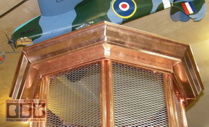
This took 12' of copper gutter to form the
eaves here, cut into 18" segments. I
bent the bottom down to form this rim that drops down over the
SS screen cage rim that will be the attachment flange. This one
section took me about 6 hours to cut and form this together.
This is 42" wide.
This is showing the finial support pipe cross
brace being made and installed. The tricky part is making sure
this will be straight and level
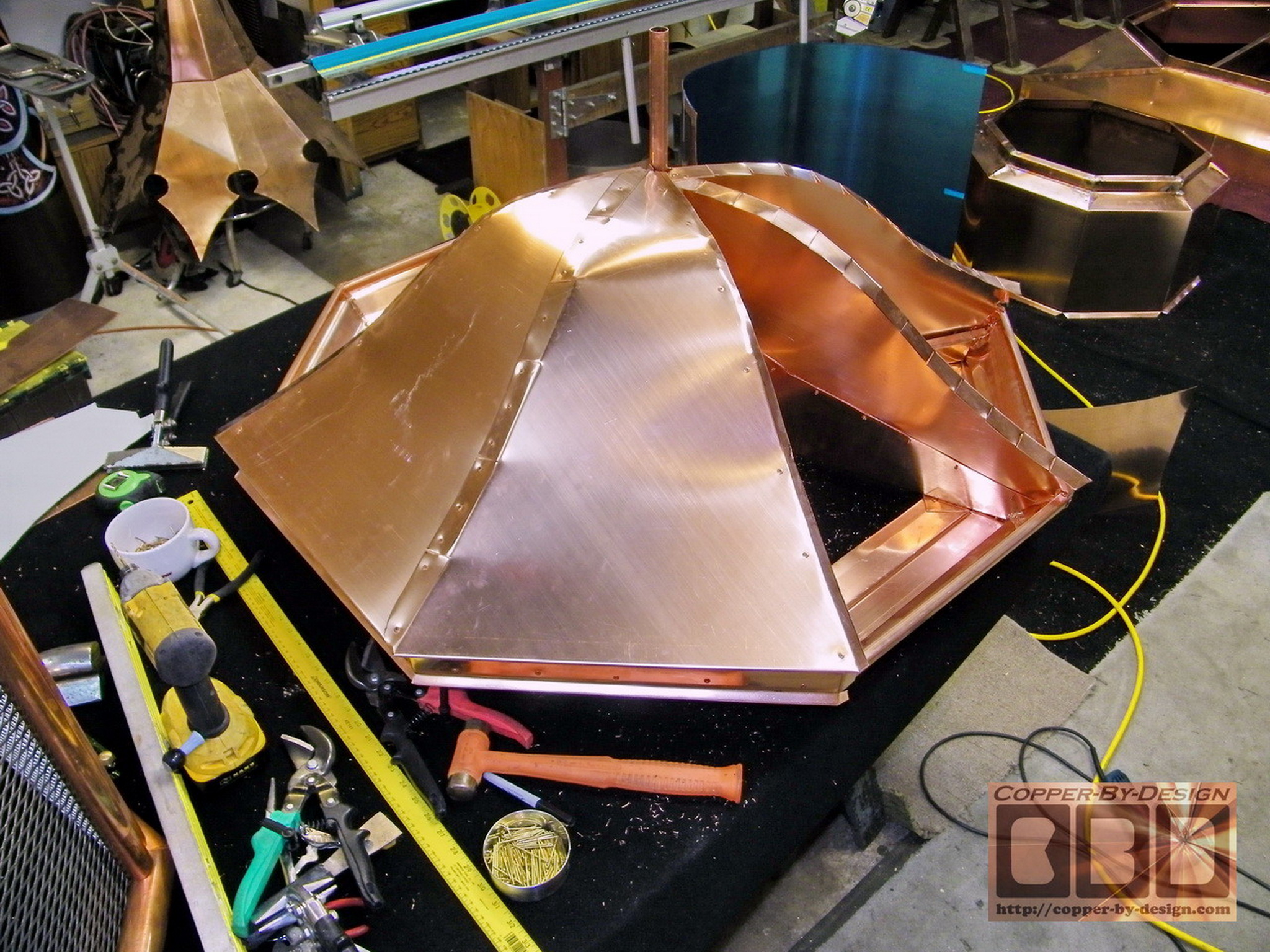
Here is the curved roof slats for the internal
supports for the roof skin being installed checking the level as
I go.
I then began to attach some of the roof skin
over these slats. Do you think this will be strong enough?
 
This is showing the seamless sheet of 16oz
copper I attached up under this woof piece to close this off
from the exhaust. It is also important for the sake of looks, as
this will be seen from underneath after it is installed on his
chimney. Also if the roof even begins to leak then the water
will be diverted outside the SS screen.
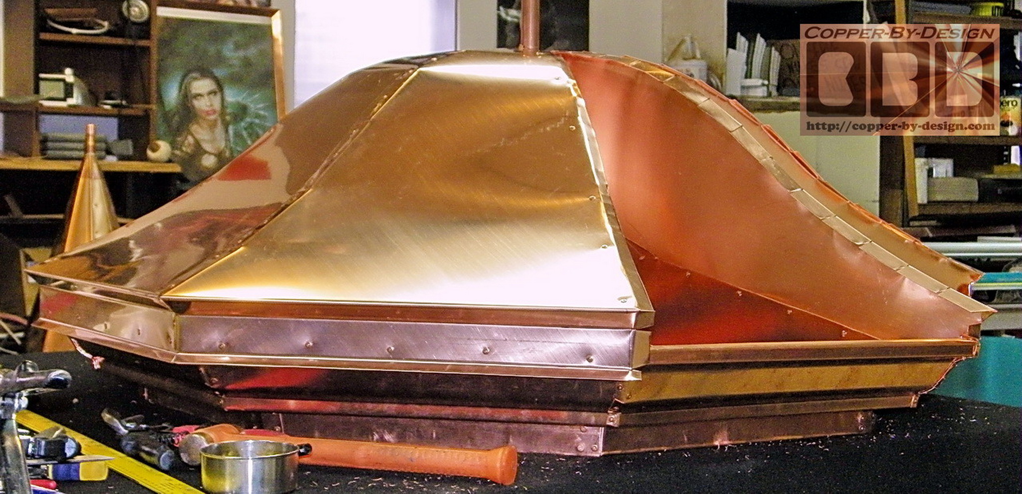
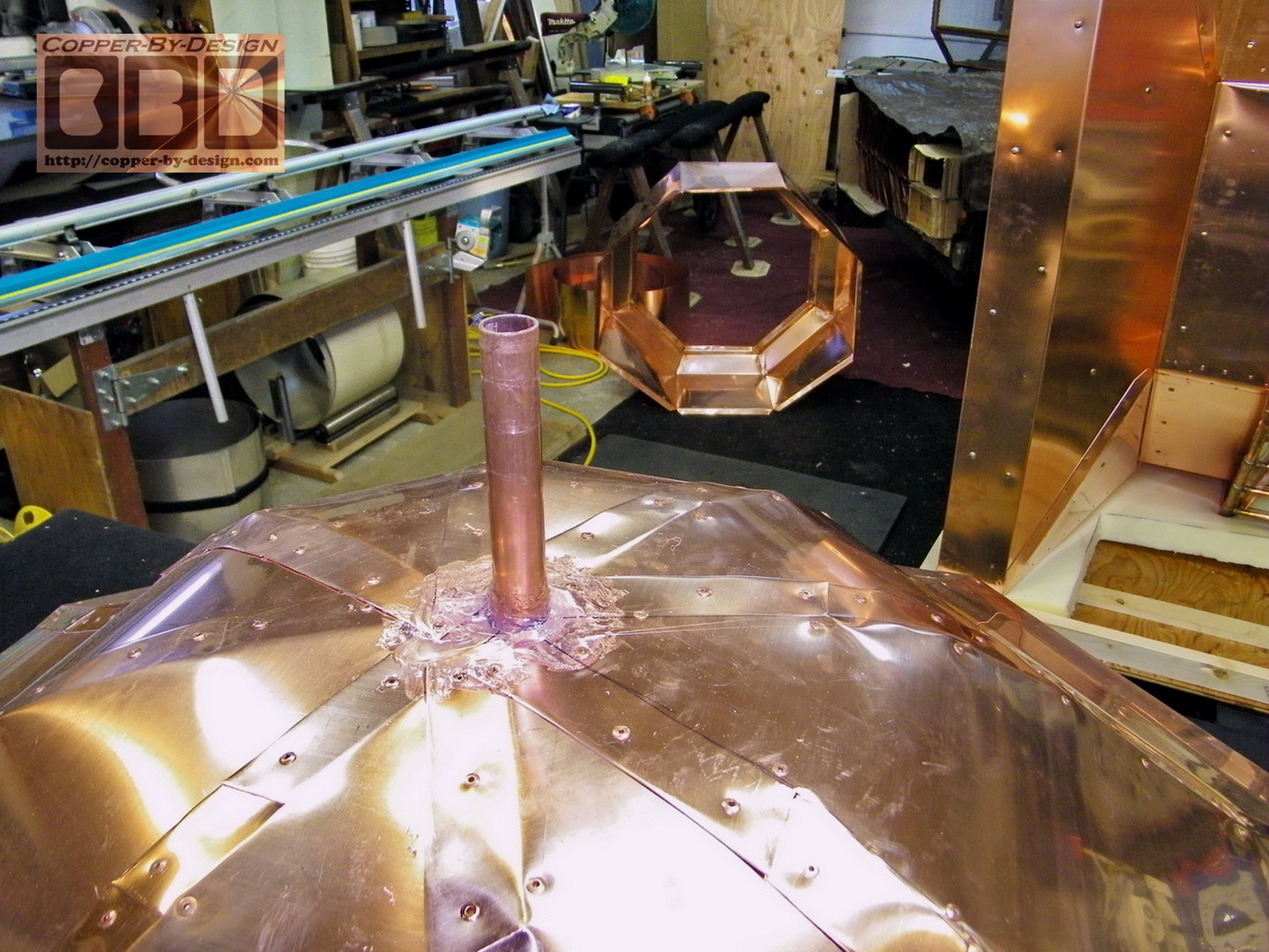
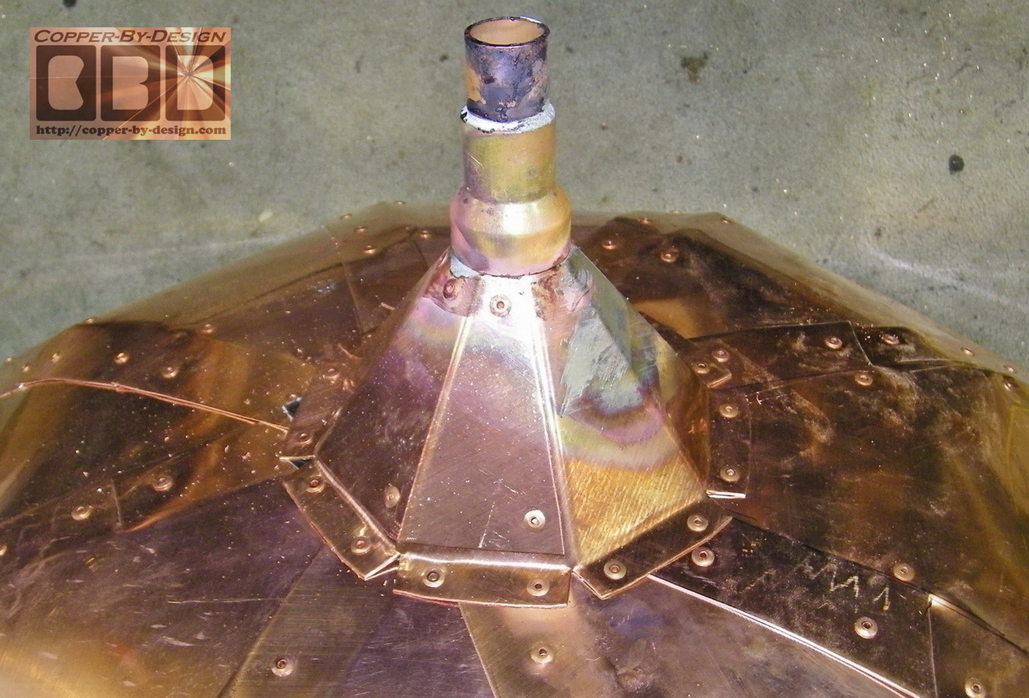
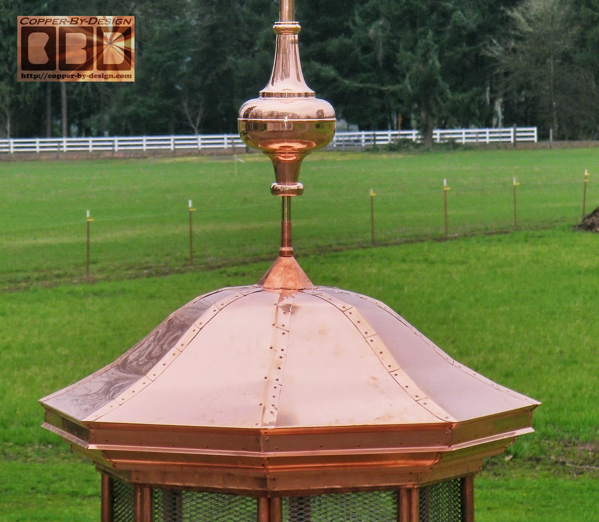
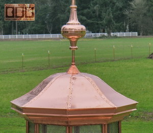
The top of this roof is pretty flat, so I made
this small come to shed the rain off to the sides and also help
support this pipe at the top. Then this round flange is soldered
to the pipe and makes a perfect seal to this octagonal cone.
This may bit be the prettiest bell shaped roof
at close inspection, but it is a good deal stronger than it
would be otherwise. I need to minimize the use of solder,
knowing that it would melt at 1/4 the temperature that this
copper can handle.
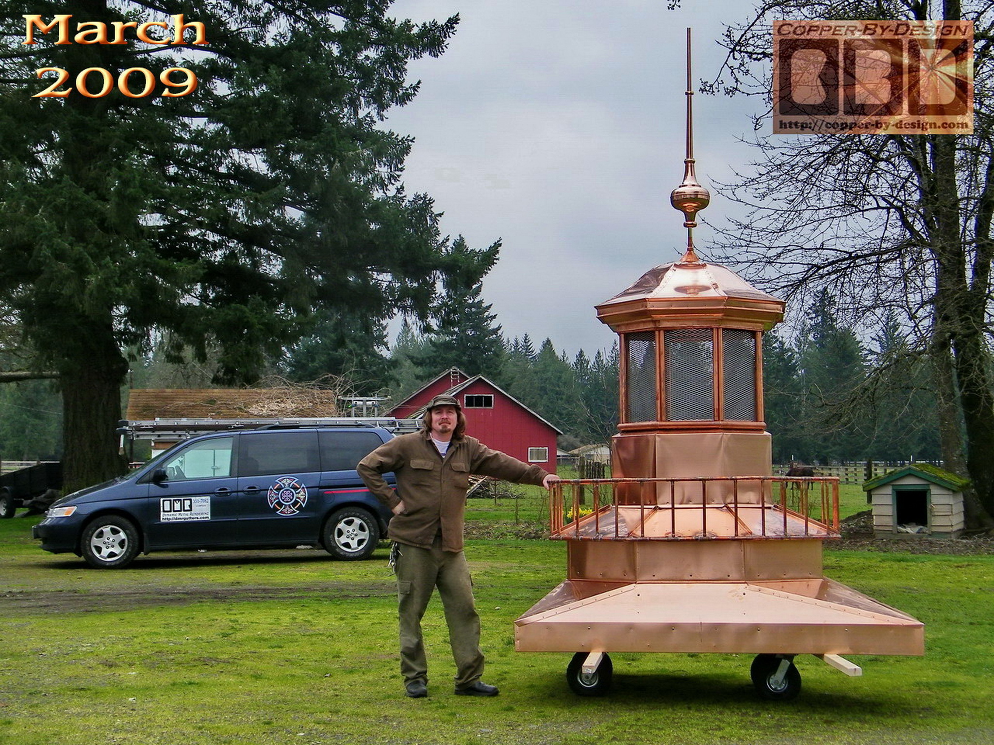
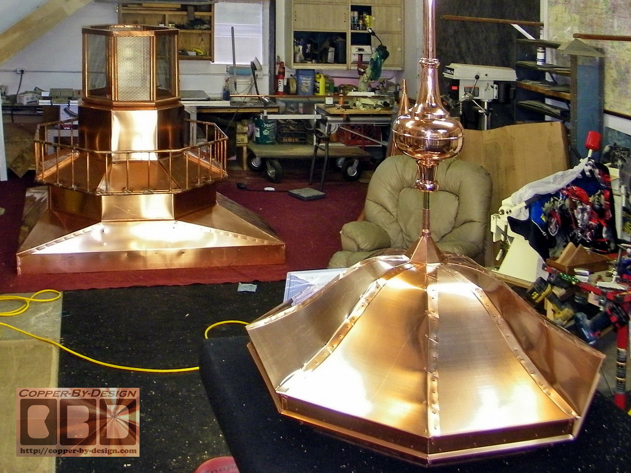
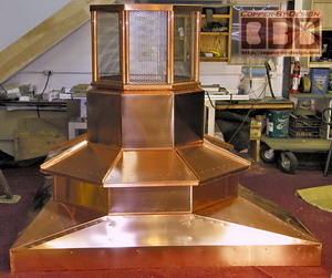
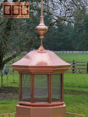
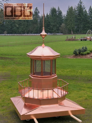
Here it is outside my workshop to get some
better shots assembled. This discoloration in the right shot is
from adding solder to help hold the railing in place after I had
used 64 rivets. This part is low enough to the exhaust screen
that it should never get hot enough to melt the solder. They
will need the extra strength if they choose to lift this from
ropes attached to this railing. to lift the 300# below it.
I know it would have looked better to have
made the wider octagonal chamber below this railing much taller,
but I also needed to keep the cost down, as I am already over
$2k over budget on this, which I have to eat, since there is a
ceiling cost of $7.5k before I started.
This is showing the crate being fabricated to
safely house this unusual chimney cap for it's long journey
across the country. I felt the need to get a 3" thick foam
cushion pad for this to rest on, so it does not get dented up on
the bumpy roads it will travel over.
|
|
This is 462.5# in all and 72.5% of this is
copper weight.
Weights and cost breakdown of these pieces are as follows:
|
|
Main base/pan weight
209# -
-
115# - wood
framework inside the pan
-
94# of copper sheet metal over the wood
-
$1,880 -
75.2 sq' of copper X $25
-
+ $395 for 5/4 x 6 hardwood boards
-
+ $225 for 2
x 2 hardwood boards
|
Lower octagon base w/railing weight 102.8#
-
33.7# of 32oz copper = 16.84 sq'
-
38# of 20oz copper = 30.4 sq'
-
31# of copper pipe railing
-
$2,414 - 102.8# X $20
|
|
Mid octagon chamber and SS screen
section
weight 71.2#
-
24.2# of 20oz copper mid chamber
-
27.4# of copper pipes
-
13.4# of SS screen = 18.6 sq' X $20
-
$1,404 - 51.6# copper and SS screen
|
Roof & finial weight 87#
-
12' of K-5 style 20oz copper gutter for eaves -
$1,512.50 - 60.5 sq' copper -
$125 for the finial mount built into the roof
-
$340 - 53" x
10" Morgana style finial w/43" solid brass mast rod w/15%
discount - 11.4# |
|
I had to make a separate smaller crate for the
SS screen chamber and the copper chamber below that, since it
would not fit inside this crate. Trust me I tried to make it
work. this crate is 8' long, 7' 4" tall, and 42" wide. If it was
even 1" taller it would not have fit in the delivery truck. This
one crate was around 700#
 We had agreed to keep this project cost within
a cap of $7,500 including the crate and shipping cost, so this
shows how my ideals of quality well exceeded the cost in
building this chimney cap with him saving over $2,000 on this
project. I did my best to build these pieces
stronger than I imagine it would need to be to withstand a
century of harsh Michigan Winters. We had agreed to keep this project cost within
a cap of $7,500 including the crate and shipping cost, so this
shows how my ideals of quality well exceeded the cost in
building this chimney cap with him saving over $2,000 on this
project. I did my best to build these pieces
stronger than I imagine it would need to be to withstand a
century of harsh Michigan Winters.
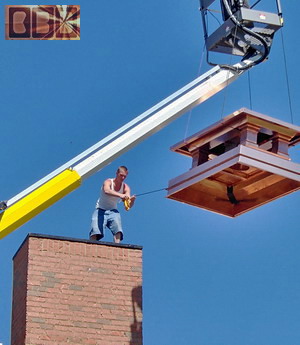
It will be no simple task to
install this over his chimney, so I also had to keep this in
mind and design these sections to be easily attached together
with the stainless steel screws I provide. Each piece has to
carefully test fitted and the holes pre-drilled for those
screws.
|
|
From: Gregory Besio <gjbesio@att.n*t>
Date: Thu, 30 Apr 2009
Subject: Installation Finished Today
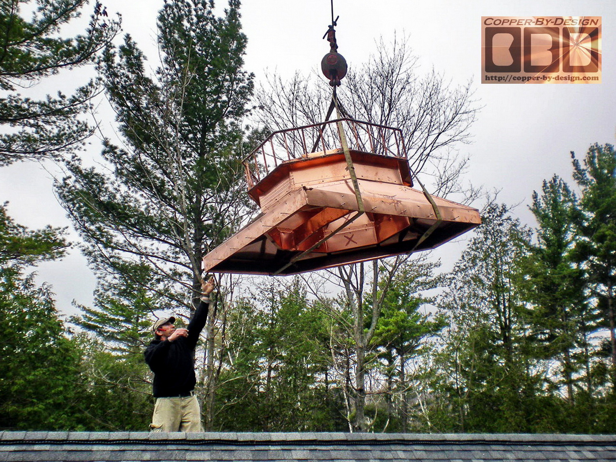
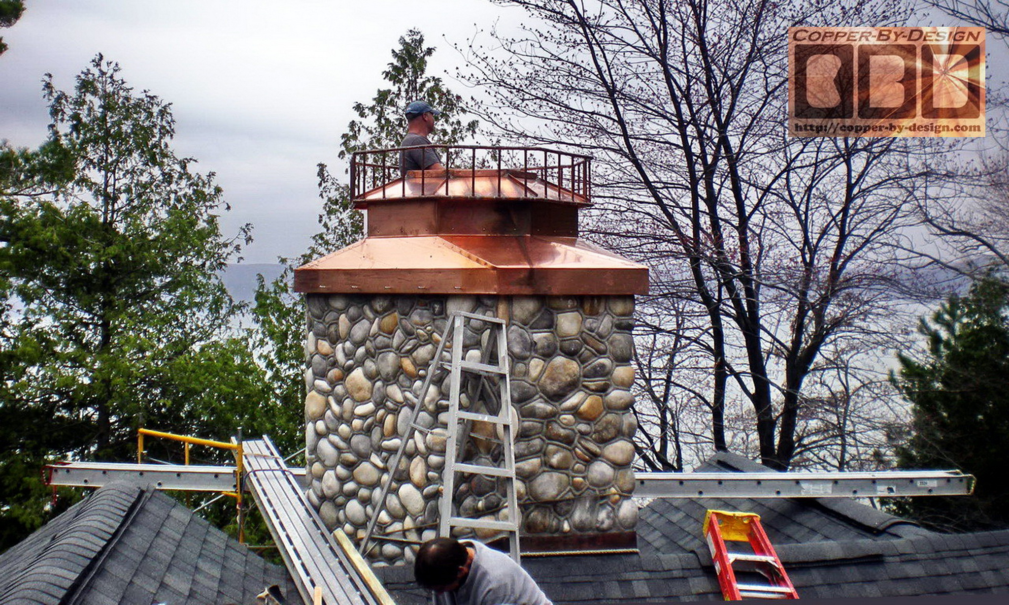
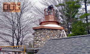
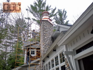
Hi David,
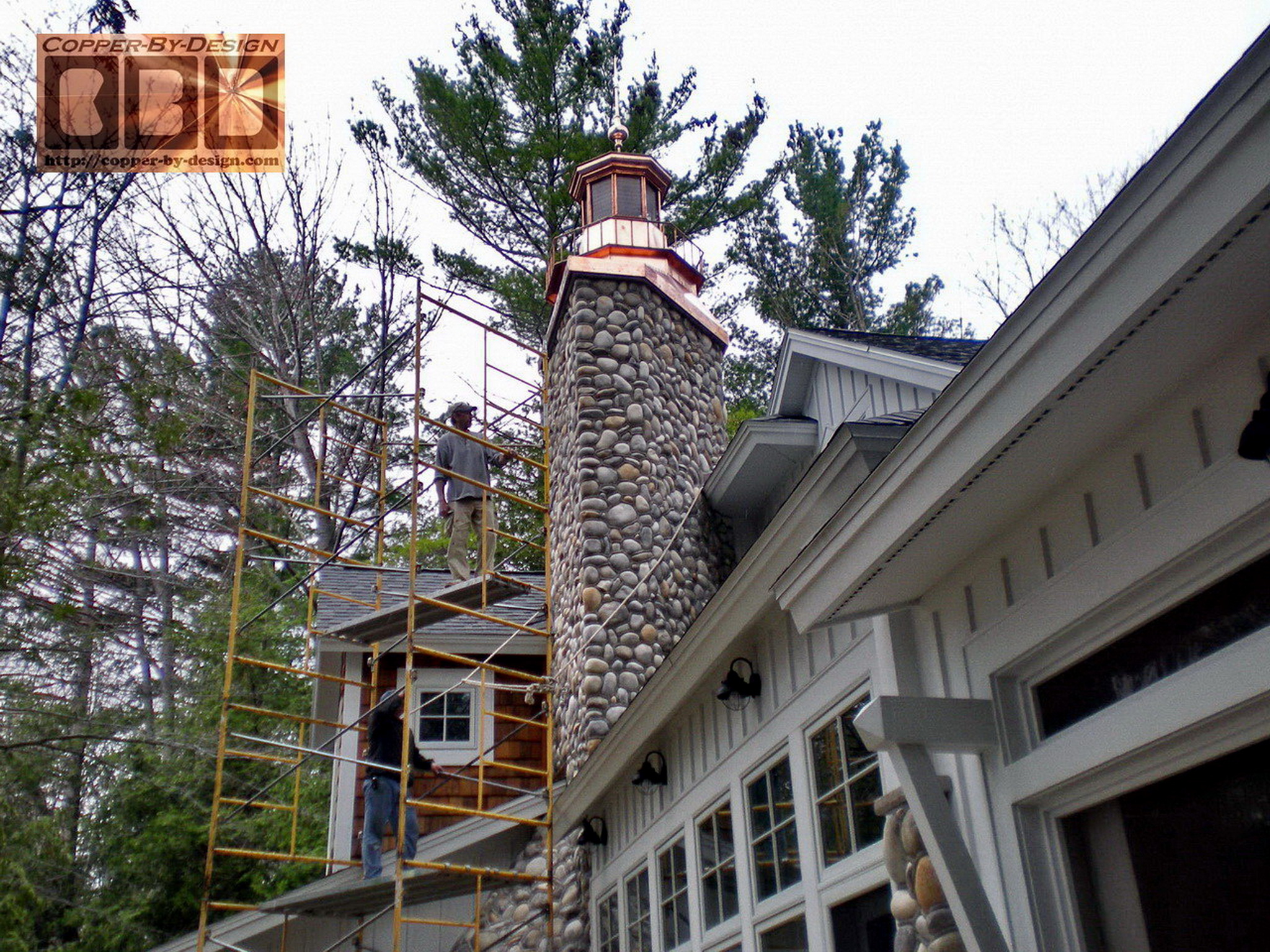
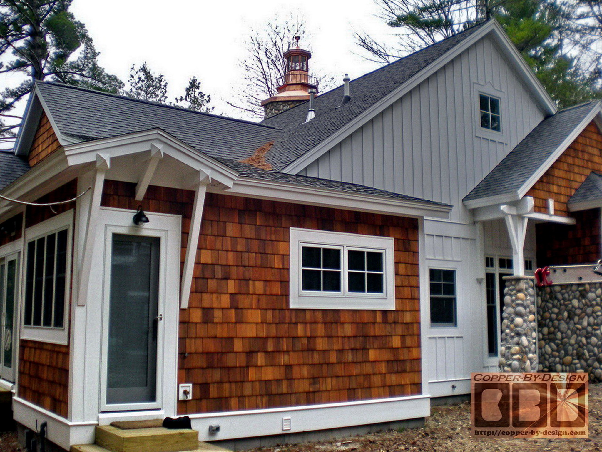
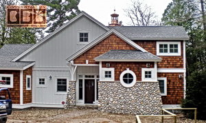
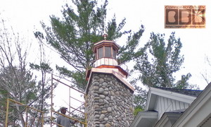
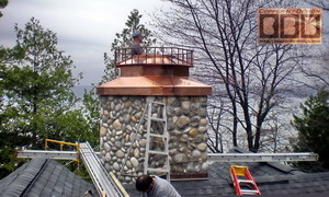
The cap was installed by my builder today.
Here are some pictures showing the installation and a couple of
views of the finished project. Looks great.
Enjoy,
Greg
I noticed in the photos the mid section got a
little bent up in transit, so I offered to rebuild it for cost,
maybe with thicker copper.
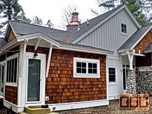
Date: Fri, 1 May 2009
Thanks for your note.
Yes, one section was slightly bent in shipping, but I think it
looks fine on the house. I don't know what measures the
installation team took to straighten it. The only reason I would
replace it would be if it impacted the structural integrity of
the overall cap. I leave it to you and Don to make a
recommendation, but think the accelerated aging adds character
to the overall look. Why don't you contact Don about details of
the install. Based on my conversations with him, it went pretty
smoothly, but his foreman would have all the specifics.
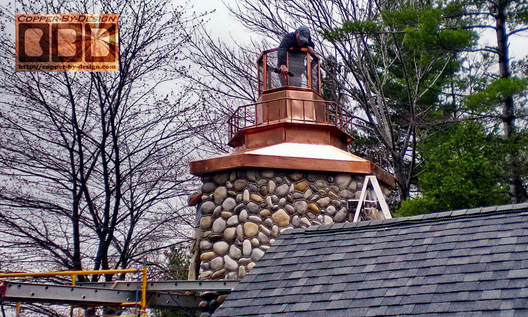
Thanks again for all
your efforts on this project. The cap really looks great -
better than I envisioned it. I think our collaboration based on
your expertise has really created a unique feature on our new
house.
Best,
Greg
|